Table of Contents
Factors Directly Affecting Molybdenite Flotation: The average molybdenite recovery in the copper concentrator for the first nine months of 1980 was 67.13%. In recent months, there has been approximately an 80% recovery of the molybdenite in the sand and slime rougher floats. The losses in the sand float are due mainly to fine molybdenite particles locked with quartz and to large nonfloating flakes. Losses in the slime float are due to finely locked material and molybdenum oxide minerals reporting as molybdenite.
All three commonly reported types of molybdenite are found in the Cuajone ore body: well crystallized molybdenite in pure veins, well crystallized molybdenite closely associated with quartz veins, and poorly crystallized sooty or smear molybdenite. The existence of the latter type in the ore was confirmed in March, 1980, when there were problems with the xanthate system. The amount of molybdenite in both the sand and slime tailings jumped approximately 50%. As soon as the xanthate system returned to normal, the molybdenite in the tailings decreased to a normal level. The sooty molybdenite generally requires assistance from xanthate for floating.
The main loss of molybdenite in the cleaner circuit normally appears to be due to overgrinding. Over 60% of the losses are routinely in the minus 37 µm (400 mesh) fraction of the Scavenger Tailing. Additionally, about 25% of the molybdenite loss is due to large flakes which floated in the high density (40% solids) sand rougher but which cannot float in low density of the cleaner-scavenger circuit. However, at times, large flakes account for over half the losses. It has also been observed that when the ore contains a large quantity of bright, fast-floating chalcopyrite, molybdenite recovery in the cleaner goes down, probably due to crowding. All of the 2.83 cu m (100 cu ft) Denver DR cells used in cleaner-scavenger circuit are covered with natural rubber making it impractical to add fuel oil to the regrind mills.
Molybdenite Extraction Plant
Molybdenite Plant Feed Thickener
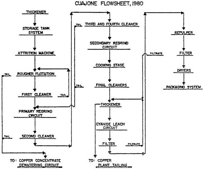
All of the copper-molybdenite concentrates are collected and thickened to 60 to 65% solids in a 49 m (160-ft) thickener. There are four draw points at the cone with two feeding each of two 100 mm lines. Outside the tunnel the two 100 mm lines are joined into a 150 mm pipe. The spigot discharge is automated using an Ohmart density gauge and a Clarkson “C” valve. Two 127 mm x 102 mm (5-in x 4-in) SRL – C pumps (one spare) are used to transfer the underflow to the storage tank distributor. Thickening to 60% solids is considered critical to the proper operation of the molybdenite flotation circuit. The frother added in the copper circuit and remaining with the concentrate water (froth) is reduced. The thickener overflow goes to the reclaim water system.
Cyanide Leach Circuit
The final molybdenite flotation concentrate passes through a Denver automatic sampler before entering a 9.1 m (30-ft) diameter thickener where it is thickened to approximately 50% solids. The thickener is fitted with a manual rake-lift and a froth ring around the perimeter. The underflow is then pumped by one of two available 51 mm (2-in) ODS pumps into any of three cyanide leach tanks. The cyanide leach tanks are 3.66 m diameter by 3.66 m deep (12-ft x 12-ft) Denver Super Agitators with conical bottoms. Normally, one tank holds one day’s production. Sodium cyanide briquettes are added to these tanks for leaching. The amount added is based on the copper assay of the pulp.
Fuel Oil for Molybdenite Flotation
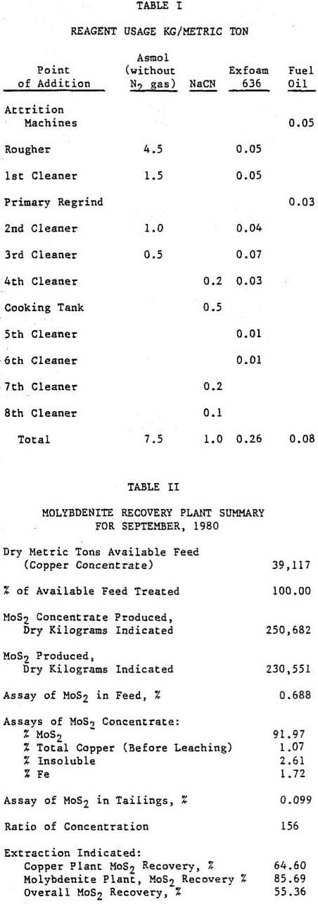
Fuel oil is added to the attrition machines and the primary regrind mill as a molybdenite collector. The majority of the time it is not required to obtain optimum recovery of the molybdenite. It is added primarily to collect the sooty or smear type molybdenite previously Collected with xanthate in the copper circuit.
The addition of the attrition machines to the circuit did not have a noticeable effect on the plant results. However, the operating staff strongly feels that the froth condition on the rougher improved with their use. The rougher flotation was operated between 20 and 40% solids before it was decided that 32 to 35% produced the optimum results. Normally, a 0.052 MoS2 rougher tailing can be produced. Vertical sump pumps were used for the rougher feed and throughout the plant for the froth products. These pumps have created surging problems. To alleviate the surging, control valves are being installed on the discharge lines. The installation of such a valve on the rougher feed line probably improved the plant recovery by 2 to 3%.
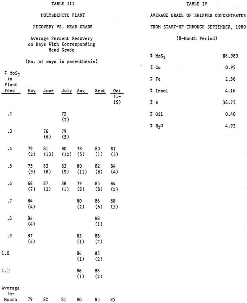
When the primary regrind mill was placed on line at the end of August, the grade of the final molybdenite concentrate immediately jumped by 5%: from about 87% to 92% MoS2. This was due to easier rejection of insolubles and iron (pyrite). The plant recovery figure also increased by 5%. In addition, the operation of the mill and the cyclone classifier have reduced greatly the amount of surging and improved the froth condition in the second cleaner. It is felt that the ball mill discharge pump box should have been designed with a larger surface area. Fairly regularly, froth overflows this box for prolonged periods of time.
Differential Flotation Process for Recovery of Molybdenite from Copper Concentrates
The problem of process development for molybdenite recovery was reffered by Hindustan Copper Limited to Ore Dressing Section, which had proven experience in the area. Laboratory tests were conducted at Ore Dressing Section using the copper concentrates received from Rakha Copper Concentrator. Since the concentrates were ‘aged’ during transportation and storage, reproducible data could not be obtained, and hence further testing was carried out on site with fresh concentrates.
The response of fresh concentrates to various reagents was tested by semi-batch kinetic tests, and the following observations were made.
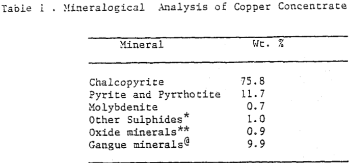
The copper concentrates containing 0.4% Mo was repulped in a surge tank with fresh water and lime was added at 1 kg/t. The slurry at 40-45% solids was pumped to a 100 litre conditioner and conditioned for 10 minutes with sodium sulphide 6 gm/l (gm/l refers to grams of sodium sulphide per litre of pulp), and then a mixture of light diesel oil and amyl alcohol LDO-AA (3:1) was added at 0.2 kg/t. The conditioned slurry was pumped at a flow rate of 10 l.p.m. to a bank of three cells of Denver No. 7.
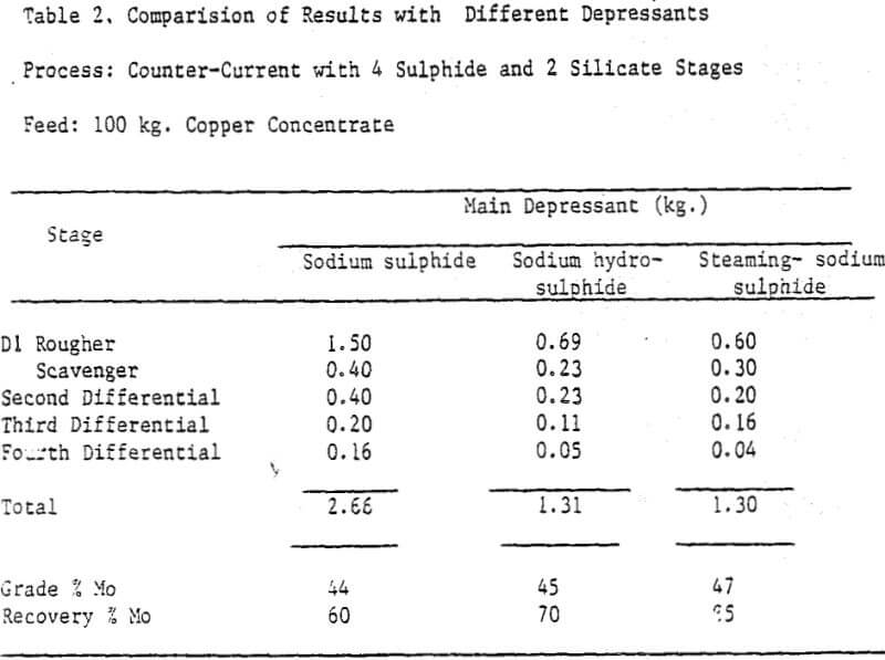
The sodium sulphide process was effective in producing molybdenite concentrates assaying 38-47% Mo with a recovery of 60-75% at an overall sodium sulphide consumption of 23-27 kg/t of copper concentrate.
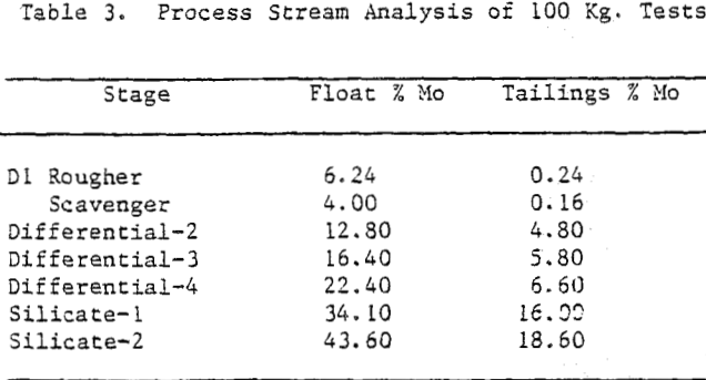
The counter-current sulphide process was simplified based on the assay of process screams of 100 kg experiments. The scavenger float was combined with the rougher float of first stage. In effect the flotation time was increased by doubling the number of cells. Multiple recirculations were eliminated by combining the tailings of second, third and fourth stages and recycling them all together to the feed stage. To ensure compatibility of recycle streams with fresh feed, stage recoveries were improved by increasing the flotation time; and thereby reducing the molybdenite assays in tailings.
Steaming of the pulp is recommended for xanthate desorption and effective reduction of sulphide consumption on industrial scale. The flowsheet is self explanatory, and as the amount of material involved after first differential stage was small, single shift operation was recommended beyond first differential stage. Reagent washing after fourth stage was recommended for regaining selectivity.
The process recommended for industrial recovery of molybdenite from copper concentrates is expected to yield a product grade of not less than 45% Mo with a recovery of minimum 65%. The final concentrate can be de-copperized by ferric chloride leaching.
Molybdenite, M0S2, occurs in porphyry copper deposits in concentrations varying between 0.020% -0.035%. By-product molybdenite technology includes two stages:
- A Cu-Mo sulfides bulk flotation; and
- A molybdenite selective flotation.
It is well known that molybdenite is a mineral with natural floatability (intrinsic hydrophobicity), and under conventional flotation technology is recovered together with copper sulfides. Subsequently, to separate molybdenite a selective flotation from the Cu-Mo bulk concentrates is performed by using depressant reagents for copper and iron sulfides.
Molybdenite exhibits intrinsic hydrophobicity due to its crystalline structure characterized by layers of trigonal prismatic coordination polyhedra, where each molybdenum atom is surrounded by a trigonal prism of sulphur atoms. Two types of chemical bonds can be established: a strong covalent bond between S and Mo atoms; and weak Van der Waals interactions between S-Mo-S layers.
This structural feature results in two types of surface sites: sites created by rupture of Van der Waals interactions, termed “faces”; and sites created by rupture of S-Mo bonds, termed “edges”.
Faces are non-polar low surface energy sites, while edges are to some extent ionic sites with a higher surface energy. Hence, faces are highly hydrophobic sites, while edges are less hydrophobic sites.
Consequently, hydrophobicity and natural floatability of a molybdenite particle is given by the faces/edges surface sites ratio. Particle size is also important because this ratio decrease with particle size. Thus, coarse particles usually are more hydrophobic than fine particles, because overgrinding contributes to create edges sites.
Additionally, fine particles of molybdenite (<10 microns) show kinetic limitations by a lower probability of particle/bubble collision and adhesion.
Selective Flotation of Molybdenite
As a result of the action of depressant reagents, this surface property remains on the molybdenite particles even after the destruction or remotion of the collector coating. Under these conditions, copper sulfides are depressed while the molybdenite floats properly with low dosages of an oily collector (kerosene, diesel oil), and some type of alkyl alcohol frother.
The main problems connected to Mo recovery in moly plants are usually linked with:
a). Fine particles of molybdenite with very low flotation rate.
b). Molybdenite particles partially depressed by lime excess.
c). Inadequate use and control of copper depressant reagents.
d). Frothing excess by residual flotation reagents.
e). Excess of recirculating load of molybdenite in some circuits.
Several depressant reagents are used in the plants. In most of them, sodium sulfide or sodium hydrosulfide are preferred, with the exception of the by-product molybdenite plants at El Salvador, which uses Anamol-D (Na2S-As2O3); and at El Teniente, which uses LR-744 or Nokes Reagent (P2S5-NaOH).
All these depressants are reducing agents, which is explained in large extend by the presence of hydrosulfide ions
(HS-). Hence, measurements of the redox potential of the pulp (Eh) are the most common way to control the process.
The choice of a copper depressant to be used in a moly plant is not a simple decision. It depends on several factors, such as: the copper sulfide species to be depressed, the collectors type employed during the bulk flotation stage (copper plant), etc.
Sodium sulfide and sodium hydrosulfide are considered as universal depressants, i.e. may be used with different copper sulfides, including: chalcocite, covellite, chalcopyrite, bornite; as well as with a number of different thiol collectors.
However, in some cases and in plant practice, the best metallurgical results can be achieved in the presence of some secondary depressants, such as: thiophosphate or thioarsenite ions. This explains the use of Anamol-D and LR-744 in some Chilean plants. Thioarsenite ions reinforce the depressant action of hydrosulfide ions on chalcocite and covellite while thiophosphate ions reinforce the depression of chalcopyrite and bornite.
In general, these types of depressant reagents require high dosages to accomplish its depressant rol, approximately 4-5 Kg/metric ton of bulk concentrate which determines a high operation cost.
One problem with depressants is their high ability to be oxidized (decomposed) by dissolved oxygen in aerated mineral slurries. The mechanism involved is catalytic and the oxidized products are inactive as depressants.
Consequently, efforts have been devoted to avoid this detrimental side reaction. Last years two technologies have been implemented in Chile to decrease the depressants consumption.
a). The use of nitrogen (inert gas) as a flotation gas phase.
b). The use of hermetic flotation machines, which produce and operate with low-oxygen recirculated air.
The first method is preferred for moly plants installed next to copper smelters, where nitrogen is produced by oxygen plants as an inexpensive by-product. The second method functions reasonably well but is difficult to maintain hermetic cells over a large period of time.
Eh in Molybdenite Flotation
In moly plants where sodium sulfide or sodium hydrosulfide is employed as unique depressant, Eh measurements in rougher tailings are around -350 mV to -800 mV by using Pt or Au electrodes (vs. Calomel or Ag/AgCl reference electrodes). In the case of Anamol-D is around -450 mV, but with LR-744 the potential is significantly less negative or less reducing: -100mV. This fact is explained by the low content of hydrosulfide ion present in this reagent.