Owing to two large falls of ground which resulted in serious accidents occurring towards the end of 1908, it became evident that the “open chamber” system then muse was unsuitable for the conditions existing in the Mount Morgan mine. It will be admitted that in all mining operations the first consideration is the economy of the system adopted, combined with its safety and ability to give the desired output. A sectional system with square sets has been introduced into the mine, in which due attention has been paid to these factors. In this paper a brief description of this system will be given. An outline of those previously used will be included, as it is necessary to understand the conditions which existed in the mine at the initiation of the sectional system. Outside the actual mining methods employed, various points that might prove of interest will be touched on.
The square set system of mining has been in use throughout the stopes in the gold ore in the upper levels of the mine since underground operations were started in Mount Morgan. In the oxidized zone the ore was of a friable nature, and in some cases running ground was encountered. In the lower levels the ground became heavier, and although the stopes were for the most part long, wide, high, and irregular, and not sectionalized, no difficulty was experienced in winning the ore, and no accident of a serious nature, due to falls of ground, occurred while mining with this system. It was then the practice to cany up the stopes to the level above, a distance of 60 to 80 ft., without filling, and only to fill after beating through. Reliance was placed on the set timbers as a support to the back.
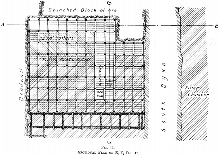
The following examples demonstrate the weight these timbers are capable of carrying. In one case a detached block of ore 60 ft. by 20 ft., weighing approximately 3500 tons, and in another a block 20 ft. by 40 ft,, weighing 2000 tons, rested on the timbers for some time. In the former case the stope was filled to within one floor of the back, and in the latter to within three.
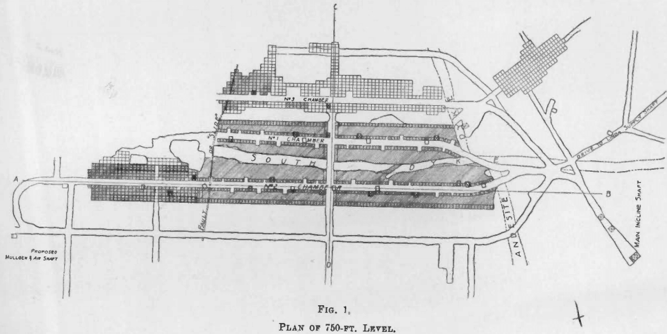
The gold ore, for the greater part, is situated on the east side of the Andesite dyke, which is a vertical dyke with an average thickness of 15 ft. (Fig. 1.)
Increasing copper values in the sulphide ore led the management to suspect the presence of copper ore at a lower level, and it was determined to prospect for this. Diamond-drilling located to the north-west, of the Andesite dyke a large amount of copper-gold ore (called in this paper copper ore). It was then decided to start mining operations on this, and a cheaper method than that already in use was sought for. The different systems of mining wide lodes in various parts of the world were examined, and the open chamber system, was adopted.
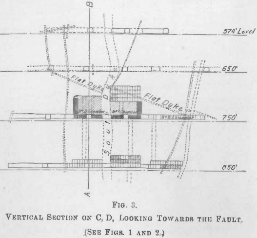
The South dyke, a vertical dyke of an average thickness of 18 ft., runs throughout that portion of the copper ore at present being worked, and is cut off at a fault about 400 ft. north-west of the Andesite dyke (Fig. 1). Levels were opened out at intervals of 100 ft. from the 650-ft. level downwards, and drives were laid off parallel to the strike of the South dyke on either side, those nearest being 30 ft. from it, and the others 60 ft. apart. To start the chambers, sill cuts were opened out from these drives to a width of 60 ft. and to a height of 9 to 10 ft., and extending from the Andesite dyke to the fault. As these were being taken out it was thought advisable to leave pillars of ore as supports to the backs, where the presence of dykes indicated weakness, and these were to be removed as the second cut proceeded. The South dyke was to
act as a support, and, as it ran parallel to the length of the chambers, could be left in situ. Poles 7 in. to 10 in. in diam., spaced 2-ft. 3-in. centres, were laid across the chambers, and close-slabbed for the purpose of forming a picking-up floor, as shown in Fig. 4.
A second cut was then started, and when this had advanced at least 30 ft., bulkheads were erected along the dead-wall to within 5 ft. of the back also 10 ft. apart along the centre of the chamber. To form the main ore-way the latter were covered with ironbark logs, 9-in. to 12-in. diam., spaced 2-ft. centres, and these slabbed with 9-in. x 2-in. timber. The bulkheads followed the second cut and could only be built to within 12 ft. of the broken ore on the floor. This distance had then to be increased to 20 ft. before the permanent bulkheads could be continued, as the longitudinal poles were in lengths of 18 ft. The stope was then filled to the level of the dead-wall bulkheads from winzes spaced about 60 ft. along the chamber, the foot of the rill of the filling being at the end of the bulkheads nearest the face. Temporary pig-styes were erected on sollars on the filling to support the back, also on the heap of broken ore and under the first cut.

The third cut was taken out in a similar manner, with the exception that now only the dead-wall bulkheads were advanced. Ore passes and ladderways were left at intervals along the ore-ways, and were built up as the filling increased in height.
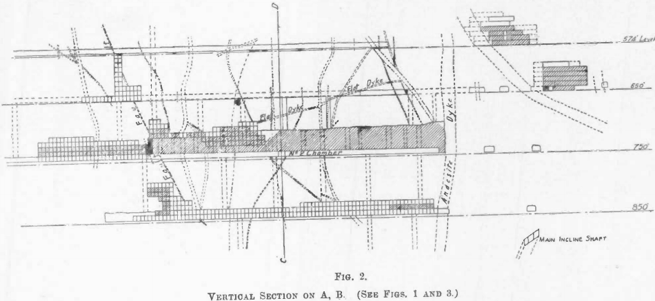
After working for about three years this system had to be abandoned, owing to the increasing “ heavy ” nature of the ground. It was found that the presence of vertical and flat dykes, heads, and “ mundic seams ” rendered it unsuitable, as too much ground had to be left unsupported in order to get the longitudinal bulk-heads in position. Figs. 1, 2, and 3 give an example of the way in which the ore-body is intersected with dykes and heads, and also show the danger of undercutting without support to any extent.
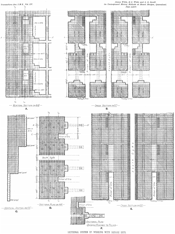
An exhaustive examination of the mine was made by experts, and several schemes suggested for its safe and economic working. After due consideration it was decided to adopt the sectional system, with square sets, proposed by Mr. James White, one of the writers. In its ideal form the system is as follows :—The ore-body is worked out in sections 30 ft. along and 60 ft. across the stope, leaving temporary pillars, 20 ft. wide, as shown in Plate LXIV. The South dyke is left in irrespective of its thickness. Winzes are spaced 60 ft. along the main drives, and are opened out to four sets, two sets being used in each section—one set as a ladderway, and the others as mullock or ore-passes. Every second section is started from a winze, and opened out, as shown in Plate LXIV., A and D, while the other sections are started from three sets, which are left open from level to level in the previous section. This is done for the purpose of saving winzing.
The stopes in each section across the ore-body are under one another on the various levels, and are, advanced together as nearly as possible.
In Plate LXIV., A, two sections are shown worked out, and the fourth section has been commenced from the winze while the third section is being completed. In Plate LXIV., B, the method of advancement of stopes on different levels is shown.
Filling is either supplied from a winze, or from one of the three sets left open in the previous section, and is carried up with the stope as shown, a row of sets adjoining the pillar on the sill-floor being left open for a roadway for the purpose of attacking it. (Plate LXIV., F.)
Plate LXIV., E, which is a cross-section taken out through the winze in the first section, which is completed, shows the advancement of the pillars on the different levels, and the method of stoping. The first 60 ft. x 30 ft. sections of the stope are completed before stoping is commenced on the intervening pillar, which is worked out on the top level before stoping is commenced on the level below, and so on. (Plate LXIV., C.)
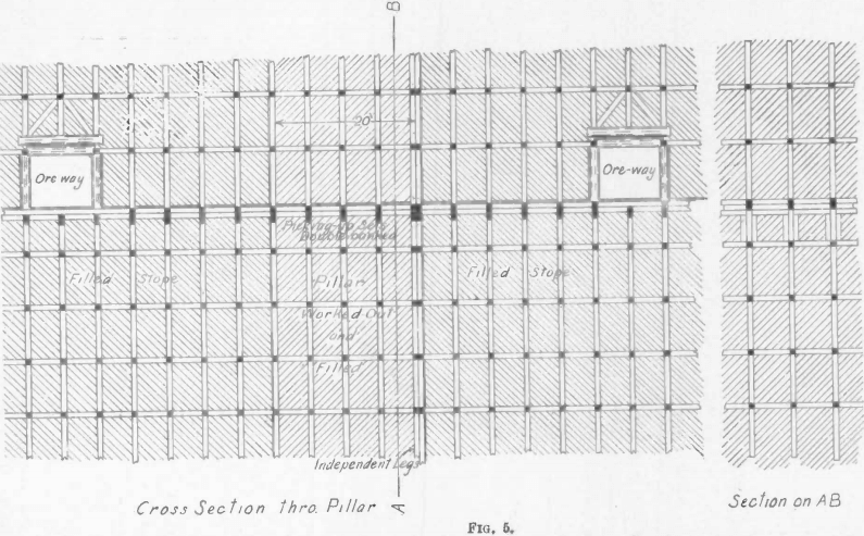
Fig. 5 shows in detail the method of timbering a pillar-section between two stopes that have been worked out. The first pillar-section, 30 ft. x 20 ft., is started from the open roadway left in the adjoining completed stope. A mullock-pass is carried forward with the stope, the roadway being filled as the stope advances. A set is left open at the end of each section adjoining the open roadway for a man-way from level to level when commencing the second pillar-section.
The following is the method of picking up the sill-floor of a stope :—When a stope in one section has been worked to a height
of 62 ft. above the level below, it is bulked if necessary for a width of 25 ft.; the remaining 35 ft. is then worked out, and the level above picked up. The bulked portion of the stope is then cut out. The timbering alongside the South dyke is shown reinforced with filled bulks built in the sets, and also the last 30 ft. alongside the pillar, but in both cases this need only be done if the ground is of such a nature as to require it.
It was found necessary to modify this scheme so as to adapt it to the work previously done in the mine. It was decided to start the sections in the north-west end of the copper ore in the vicinity of the fault, and advance them towards the Andesite dyke, and at the same time towards the main inclined shaft, through which the ore is raised, so that trucking ore and filling should, as far as possible, be on solid ground, and not over depleted stopes, this being also the most favourable direction in which to attack the ore under the Flat dyke, shown in Fig. 2.
To start the system it was necessary to sink winzes from the various levels. One chamber on both the 850-ft. and 750-ft. levels had at this time been opened out only on the sill-floor. The floors were levelled off, and square-set timber erected. In the remaining chambers at least two cuts under the chamber system had for the greater part been taken out. Filling was then introduced wherever possible, and in most places was hand-packed to the back. When square-sets were to be erected on filling, 12-in. x 4-in. hardwood sollars from 12 ft. to 24 ft. long were first laid down close together, with their length across the chamber, care being taken to stagger the joints and to keep the timbers from resting on the bulkheads or passes, so as to ensure even shrinkage. Ordinary caps and struts were then laid on top of these as sills. Where a cut was advancing under the chamber system, square sets were erected as close to the face as possible. Temporary pig-styes of 9-in. x 9-in. timbers were built up under the back of the previous out; then the cut was continued, the pig-styes being removed and set timber erected. This was done to secure the ground and allow of paddocking and hand-packing the stope on either side of the ore-way, as shown in Fig. 4. The open sets were left over the ore-way to keep unnecessary weight from it in the event of any large displacement of ground, and also to facilitate opening up the sections.
Drives are made 10 ft. wide by 9 ft. high, two machine drills being employed. Very little timbering is required, except where passing through dykes. Drive sets are spaced 5 ft. centre to centre, and 2-in. round-backed slabs are used. Legs and caps are not less than 10 in. in diameter.
When timbered, winzes are 8 ft. x 6 ft. inside measurement; joggled slabs 9-in. x 3-in., resting on 9-in. x 5-in. frames, are used. The latter are spaced 20 ft., except where the ground is bad, in which case the distance apart is diminished. These winzes serve as mullock-passes, and, although they are made large, the filling occasionally hangs up in them. Their size also permits of sinking with two machine drills.
The square-set timbers are 9-in. x 9-in. ironbark or spotted gum, which is plentiful and easily obtained in the surrounding district. Logs 13 in. in diameter are delivered at the company’s sawmill at 10d. per running foot, and are there cut to size, ready for erection in the mine. The slabs obtained in squaring the logs are used underground.
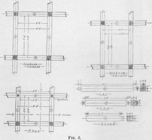
The legs are 7 ft. shoulder to shoulder, except on the main level floors, in which case they are made 8 ft., to give sufficient room for chutes in the main ore-ways through the stopes. Caps are spaced 5 ft. and struts 6 ft., centre to centre. The detailed dimensions are shown in Fig. 6. Struts run across, and caps along the stope. In laying down the sill-floor the ground is levelled, and then ordinary struts and caps are laid down as sills, the space between being packed with broken ore, which is recovered when the floor is picked up. The sets are erected, and the floor close slabbed, first with 9-in. x 2-in slabs, and then with round-backs. The floors of ore-ways consist of two layers of 9-in. x 2-in. slabs. At one time sills long enough to carry three sets were used, but these have been discarded for many years as inferior to short ones.
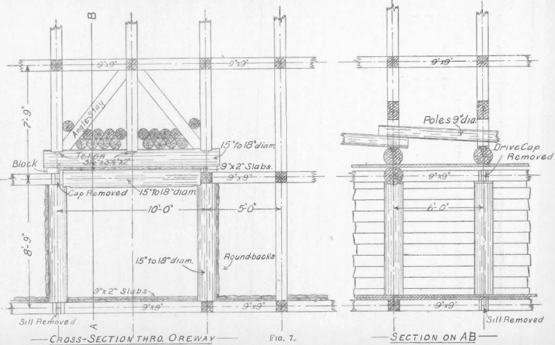
The ore-ways on the main levels are made 10 ft., or two sets, wide, and in this case long sills are used between the legs. Along the ore-ways legs 15 in. to 18 in. in diam. are substituted for 9-in. x 9-in. timber, and the caps are double and of the same dimensions. On account of this, shorter legs are required over the main ore-way. These are mortised into the top cap. Angle-stays are put in from the top of the centre leg to the bottom of the
outside legs, thus relieving the caps of a good deal of weight and throwing it directly on to the drive-legs (Fig. 7). The sides of the ore-ways are covered with round-backs. One thickness of 9-in. x 2-in slabs is laid between the caps, the upper one being held in place with two ¾-in. diam. iron dowels driven through it into the main cap near the legs. The sets are then erected, and poles laid close together on top of the upper cap, the ends of one set of these overlapping those of the next. In opening put the first 60-ft. x 30-ft. section the drive on the sill-floor is cut out to about 30 sets in the vicinity of
the winze, which is then stripped to the level above to a size sufficient to admit of four or six sets being erected on each floor, the timber being carried up as the stripping proceeds. In the former case two and in the latter three of these sets are in the succeeding section. One set in the winze is lined with 9-in. x 2-in. slabs to form a temporary ore-pass, which is afterwards converted into a mullock-pass for filling the section, the other sets being left open for ladder and timberways. While the winze is being opened out, the remainder of the sill-floor is being stoped. On that side of the stope adjoining the 20-ft. pillar the ore is taken out as neatly as possible, only leaving sufficient room for the sets to be erected. Alongside the pillar of ore the set timber is slabbed on the inside with round-backs spiked on, and with 2 in. to 3 in. spaces between them, but where the pillar has been cut into under the old system, the outside also is slabbed with round-backs, the space between the pillar and slabbing being tightly packed with broken ore, which is recovered with the pillar. Alongside the South dyke no slabbing is required. That end of the section from which the next will be started is paddocked off, with the exception of three sets, which are left unfilled from level to level for the purpose of giving access to each floor as stoping proceeds. Ore-passes are formed in the square sets where necessary. They are lined with 9-in. by 2-in. slabs, placed vertically, and ladderways are left up and down alongside the mullock-passes.
Particular attention is paid to keeping the timbers plumb and square, and also to the blocking of the walls, faces, and backs, and it is insisted that this should be done at the joints of the sets alone. Blocks, 9-in. x 9-in., are used, and are wedged as tightly as possible. Should the distance between the legs and the wall be 2 ft. or more, hitches are cut. As soon as sufficient ground has been taken out to admit a set, timber is placed in position, except on the sill-floors, where the sets are at times kept from 10 ft. to 12 ft. from the face. This is to minimize the danger of legs being broken by firing.
It occasionally happens that the set timbers show signs of failure under vertical pressure, in which case double-banking is resorted to.
This consists of reinforcing the caps, struts, and legs with the timber recovered from old stopes in the open cut, and tightly wedging them between the caps and struts.
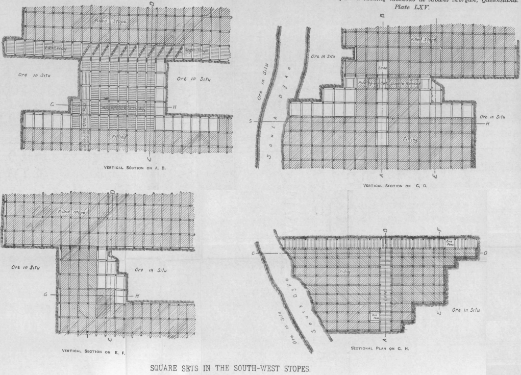
Should side pressure be expected the tenons are reinforced with 9-in. by 2-in. slabs spiked on to the struts or caps between the legs, and, if necessary, angle-stays are used, as shown in Plate LXV. With angle-stays there is a tendency to lift the caps or struts, but this is prevented by tight blocking at the backs.
When the second floor is nearing completion, the filling is allowed to rill as far as possible from the pass. A temporary chute is then put into the mullock-pass on the second floor, and filling trucked into the floor below. The chute is removed from floor to floor till the stope is filled.
Should bad ground be met with, paddocking and hand-packing are resorted to on the highest floor.
Mullock, which is particularly suitable for filling, as it packs closely and is not subject to great shrinkage, is supplied from the open cut through two main mullock-passes. These passes, when full, contain sufficient filling for three days’ work, and thus ensure a supply in the event of the mining of mullock ceasing for a short period in the open cut, as occasionally happens during wet weather. All dyke and waste material broken underground is utilized as filling. In one stope where sollars were laid on filling 50 ft. deep, which has since been carried to 80 ft. above this, very little settlement has taken place, and no difficulty has been experienced in keeping the timbers regular.
As the second floor is cut out loose 9-in. x 2-in. slabs are laid on top of the sets. This is to prevent loss of ore in the filling and for general convenience in the stope. These are removed from floor to floor as the stope progresses.
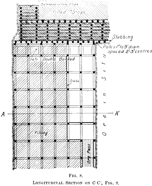
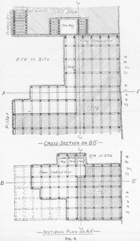
The sill-poles laid down under the chamber system have been picked up on the 750-ft. level alongside the South dyke, for an area of 60 ft. x 30 ft., with ease and safety. There is no perceptible movement of the timbers on this level, although there is 130 ft. of filling above them. The picking-up floor was tightly hand-packed. The method of picking up is shown in Fig. 8.
In the gold ore, to the east of the Andesite dyke, many levels have been picked up under square sets at various tunes without difficulty. An illustration is found in the south-west stopes, and is shown in Plate LXV. The ground is cut out for two sets wide com-
pletely across the stope, and is carried up to the sills above. As the mining proceeds, sets are slabbed off to within one set of the face and filled. This is completed before the next strip is started. Temporary open ways, which are afterwards filled, are left in the centre back to the ladderways and passes. In this instance the picking-up floor has settled as much as 12 in. This stope extends
in some places to the open cut for a height of 210 ft. above the level being picked up. In other places it does not rise to the surface. In the latter case particular attention is paid to the blocking at the back, so as to keep it tight.
In No. 2 chamber, 750-ft. level, on the north-west side of the fault, gold ore, in which a stope has been opened up, occurs adjoining the first section in the copper ore in that chamber. As some of the sections in the latter will be completed both above and below the 750-ft. level, before this gold ore is worked out, it was decided to advance this stope in the opposite direction to that of the copper stopes, so that the ore and filling for it should not pass over the worked-out portion of the sections in the copper ore. The ore-ways through these stopes are being connected to drives running parallel to them in solid ground (Fig. 1).
The sill-floor of this gold stope was cut out under the chamber system for a length of 170 ft. and width of 60 ft., and timbered with square sets. This is being taken out for its full length and width for a height of five floors, which is to allow the first section in the copper ore to get sufficiently advanced before the sectional system is started in this stope. Although the back of the stope is flat and long, it is strong, as the ore-body has been displaced by the fault, and neither the South nor Flat dyke occurs in this part of the mine.
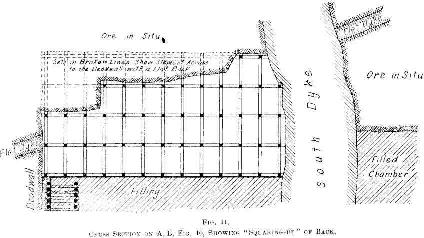
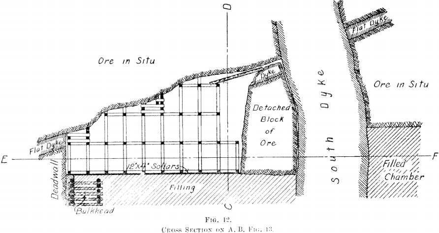
Fig. 10 shows the intersection of the South and Flat dykes with the ore-body, and the method of winning the ore from under the latter. As the ore has been undercut under the chamber system from the Andesite dyke to the fault, the presence of a vertical transverse dyke or head renders the ground under the Flat dyke still more difficult to mine. The stope has been filled up close to the back for nearly its full extent.
The following is the method of mining this ore —It must be pre-supposed that the ore has been taken out, leaving a face across the stope with a slight batter, and that square sets are in place, being erected vertically from the foot of the face up to the top of the Flat dyke, and that the sets have been filled, leaving those nearest the face open, and lane-ways back to ore-passes and ladder-ways.

As a rule, two sets are then advanced along the dead-wall, after which the stope is cut across to the South dyke for this width, sets being erected to the back as soon as there is sufficient room.
Where the Flat dyke is two sets or more above the sill-floor, the ore under it is worked out from the top of the dyke downwards with a batter. Poles are placed over where the men are working to protect them till these sets can be put in. Should the top of the Flat dyke be more than 2 ft. above the set below, but not high enough to admit a set, temporary bulks are built on the timbers so as to support the back. The filling is kept as close to the face as possible. The ore is then cut out from the South dyke back to the dead-wall to the height of the highest set, to form a flat back. Ironbark poles, 6-in. diam., running the length and breadth of the stope, are bolted to the legs so as to steady the timbers. Where the ground above the Flat dyke is found to be particularly good, a strip four sets wide has been taken out across the stope. The working face is kept not less than 30 ft. in advance of the 60-ft. x 30-ft. section, which is following it. It will be seen that this is a modified form of the sectional system, in which the length of the section has been reduced in general to 12 ft.
Up to the present none of the pillars left under the sectional system have been mined, but no difficulty in recovering them is anticipated.
The chief features of the sectional system with square sets, which combine to render it successful at Mount Morgan, are :—
- Its safety, which is due to—
(а) The small area of the roof of each section.
(b) The support given by the pillars while required.
(c) The strength of the square set timbers.
(d) Its flexibility—it being possible to remove, where necessary, ground intersected with dykes and heads, without undercutting. - Its adaptability to the open chamber system of mining, sections being started either on filling or sill floors, and the pillars left under the old system being utilized.
- That no more ground need be unsupported by timber at any time than will admit of the erection of one set.
- That, by slabbing over the sets, the miners are protected, whilst boring, from loose pieces of ground.
- That the filling packs closer than if rilled, due to the mullock being trucked in floor by floor and packed under the struts and caps, and left for some time before the next floor is filled, during which it settles as it is tramped over and subjected to vibration by the machine-drills and firing.
- That the great number of faces that can be worked in a stope, the quickness with which machine-drills can be rigged, and the fact that the floor on which the miners are working is free from broken ore (this being shot down on the floor below), all contribute to give the machine-drills a large breaking capacity, with the result that as much as 1000 tons of ore a month is frequently broken per machine.
- That the ore can be removed to the passes, if necessary, while mining is proceeding.
- The ease with which filling can be run into the stope and distributed, and with which it can be paddocked-off and hand-packed to the back.
- That the working stopes can be well ventilated, as the open sets left for mullock-passes, ladder and timber ways, need be the only connections from level to level.
In the main drives and ore-ways trucking is done by electric motors to pockets over the main inclined shaft. These pockets are tapered from 8 ft. x 8 ft. at the top to 8 ft. x 12 ft. at the bottom. They are timbered with 9-in. x 3-in. joggled slabs and 9-in. x 2-in. vertical slabbing.
Should a large quantity of ore hang up in a pocket over the main shaft it would probably cause serious damage to the shaft timbering when freed, and it is to minimize the danger of this that they are made in this shape ; neither is there so much wear and tear on the timbering due to friction as in vertical pockets. The main inclined shaft starts at 318 ft. and goes to 1040-ft. level at a uniform grade of 1 in 1. It is connected with all levels from 450 ft.
down, with the exception of the 512-ft. level. The shaft has three compartments, two of which, 5 ft. 6 in. x 6 ft. 6 in., are used for raising ore, and the third, 3 ft. x 6 ft. 6 in., for a stairway. The sets are of 9-in. x 9-in. hardwood spaced 5 ft. centres (Fig. 14).
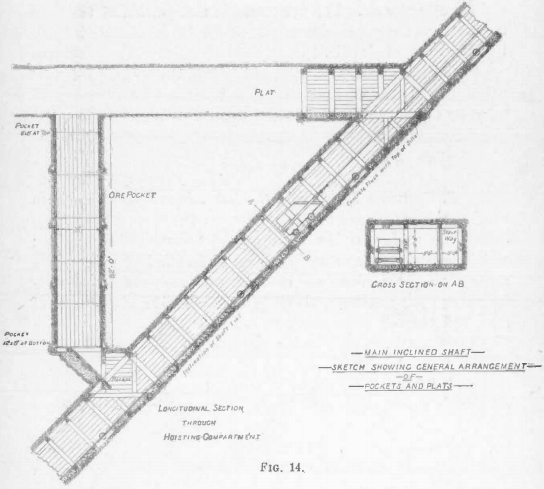
The door is concreted flush with the top of the sills, and the tracks are laid with 40-lb. rails, with a gauge of 4 ft. 3½ in. The ore is hoisted in self-dumping skips, capable of carrying 5 tons.
Timber, steel, and other supplies are sent into the mine through the Linda supply shaft, which starts at 450-ft. level, and serves all levels from 650 ft. down. The inclination of the shaft is 1 in 3, and there is a double track of 2-ft. 2-in. gauge, which is the standard throughout the mine and on the surface. This enables timber to be sent direct from the sawmill to the level on which it is required. This shaft is also to be used for lowering and hoisting men.
A shaft is being sunk with two compartments, one for mullock and the other for air. This is situated in that, portion of the mine furthest from the present downcast, and should considerably increase the circulation of air (Fig. 1).
All mining is done by contract, and most of the filling. Mining is paid for by the set or toil, driving and winzing by the foot, and filling by the set.
Discussion
Mr. F. Danvers Power said the first thing that struck one on hearing this paper read and going through the mine was the large quantity of timber employed in the present method of extraction ; and the question that naturally arose in one’s mind was, whether in many parts of the mine some other method, such as the slice-and- fill, the ore being taken out in slices say 10 ft. wide with an arched roof, and the filling kept well up, could not be used with equal safety to the miners, and far less expense to the company. That branch of geological survey termed in another paper “ Mine Sectional Analysis” should be of the greatest use in determining the proper way to approach blocks of ground bounded by faults and dykes, and also in giving an idea as to which ground should be treated as treacherous and which as fairly safe. He noticed that hardwood was employed as being superior in strength to Oregon pine, and yet it was weakened by using it squared, which must cut across the grain in places, instead of using it round. In the Hartz mountains, Germany, where the square set system of timbering originated, they used round timber, and in many other places, both in Australia and the United States, they now used round timber in preference to squared, full advantage being taken of the shape of the timber at the joints by bevelling the wood. The Mount Morgan caps and struts were of different lengths. In some mines they saved a little timber by giving both sticks the size of the larger member, or by having the struts of smaller scantling. It was mentioned that the long sills which stretched over three sets proved inferior to the ordinary short sill for the sill floor. Was this because it was found more awkward to handle the longer sticks of timber, or were there other reasons that counterbalanced any advantage in picking up longer sills when coming up from below ? Referring to Fig. 7 of the paper, he would like to know what was the objection to allowing the angle stays shown in the short set above the “ oreway ” or gangway, to take all the weight from overhead and transmit it to the legs ? A centre leg as shown would transfer much of the weight vertically to the weakest part of the cap, and he understood these caps had been known to break. Were not the slabs between the two caps difficult to replace in case of renewal being necessary ? If they were afraid of the angle braces breaking the tenons of the side legs by lateral thrust, then it looked as if the packing was not so tight as one was led to believe. It was well known that the best system of timbering could only steady ground, and was no good for holding up great weights. The best one could do was to control a block of ground. Filling helped to reinforce square sets, but it will shrink, even when hand packed, and it was notorious that it could not be tightly packed in a network of timber, and therefore it only served as a partial support. He had seen the timber of gangways split into match wood, by the fall of a comparatively small block of stone on the filling of square sets three or four floors above. The authors had mentioned that the mullock packed closely, and that their main mullock pass holds a supply for three days. Under these circumstances, he asked was there not fear of the mullock passes hanging up ? By leaving pillars of ore to be subsequently extracted, were they not artifically making conditions somewhat similar to blocks of ground bounded by dykes and faults ? Such pillars had no lateral support, and when the upper level was worked out, and the pillar undercut, the ends were the only support left.
Mr. James Hebbard said, having seen the very excellent -system of mining adopted at Mount Morgan and learned its excellency from the immunity from accident which had resulted from it, he thought that discussion of the particular paper before them could be very much shortened: the immunity from accident being the clearest possible proof that the system adopted was as it should be for the protection of the men who were engaged in the extraction operations. He had the pleasure of visiting the mine during the day and he felt free to say that in his opinion the problem of working the particular character of ore body under review had been tackled with a view to the maximum amount of safety for the men, and altogether in a most excellent manner. Wandering through the stopes, one was struck with the similarity to the general idea which existed at Broken Hill. He spoke as a Broken Hill man, and a strong advocate of the system adopted there, with their various modifications; he could of course only say that it struck him as a very admirable one. He expressed this opinion with the knowledge that they had a clear proof of its benefit by reason of the immunity from accident. Looking at the Mount Morgan system generally and with a very limited knowledge of the general arrangement of the ore body, he expressed any opinions regarding what the future working of the mine on that system would be with a very great amount of diffidence, but it appeared to him that could the system have been laid out so as to leave the proposed pillars abutting against the dyke that run through the centre of the ore body, instead of parallel to it, it would not only have made for future safety and stability, owing to the very strong natural support which would be given by the dyke through its remaining intact, but they would have had, for at least 60 or 70 % of the total ore to be extracted on any particular level, the added support of the pillars or piers abutting on the dyke. It therefore seemed to him, from a cursory glance of the lay-out, that the system would have been somewhat improved by having the pillars transverse to the dyke, instead of parallel to it. In regard to the reversion to square sets instead of pigsties, he might be allowed to express the view that in this particular they had erred on the side of excess caution. Theoretically, the back of a stope was supported by the timber placed therein for that purpose. In practice, however, where mullock filling was adopted, ore in the back was never supported and must necesarily fall, unless of such, a shape or strength as to be self-supporting. It followed, therefore, that in the ordinary operation of mining, even though the greatest possible care was taken in wedging between the timbers and back of the stope, the shrinkage of the timber and the added drag of the mullock invariably left the back unsupported. This was not so evidently the case where bulk-heads or pigsties were used because places permitting wedging up were always more accessible between the pieces forming layers in the pigsties than immediately over the top of the sets. Pigsties were therefore more effectual in preventing large movements of ground than anything in the way of square sets. To make his meaning clearer he would cite one example, viz.:—a regular system of bulk-heads spaced equi-distant in all directions gives support in the shape of a pillar as compared with the post forming one of the sets, and in addition, should reinforcing be required it can always be done by booming or bulking between the pigsties, thus distributing the weight of the back over the pillars and affording a more general support than can be got by struts or caps forming the beam between the posts. The movement of a large body of ground from the back, such as would occur in this and every other large mine in which there were defined faults or weak places in the general structure of the ore body, would certainly crush every set of timber used in the back of the stope if square sets alone were relied on. He had seen this happen so many times that he felt sure it would occur again. He had seen it repeatedly. The whole top run of the stope of square sets would be splintered to absolute matchwood by a slight movement that could not in any way be termed a creep, and he had seen, in similar ground, an area of 200 ft. x 180 ft. set off in the same manner on bulk heads, and the total movement would not be 6 in., and no damage done. It seemed to him therefore, that in the face of the certainty of large movements in a way that might be expected, the position in the Mount Morgan mine would be better safeguarded by a return to some modification of the bulk-head system they formerly used in the mine. He expressed this opinion from a very large experience in the matter. The circumstances, he admitted, were somewhat different at Mount Morgan to what they had at Broken Hill, particularly in the Central mine; but they were not different in one particular, and that was that with square sets the back was never supported in practice whereas with bulk-heads they could be. He would guarantee that they could go through the Mount Morgan mine tomorrow, notwithstanding the extra care that was evident in safeguarding the men and the workings, and on examining the back of any of the stopes they would find that a large proportion of wedges placed between the top of the set and the back of the ground were loose. If this were so, of which he had no doubt, it would very clearly support his contention that by using square sets combined with mullock filling, the back was never really supported in practice and invariably gave way unless inherently strong enough. With the system of bulk-heads set up equi-distant, explained in his earlier remarks, and joined by beams in the form of lagging in the same way as they lag the back of their sets, they did as an actual fact in practice complete the connection between the mullock filling, per medium of the bulk-head and the back by constant wedging up to a point where the wedges could be easily reached and constantly attended to, so that there was a chance of better support being obtained altogether apart from the fact that the bulk-heads were better able to support the weight of any falling ground than the square set timbers. At Broken Hill, in ground that was a long way more liable to flake and flaw than at Mount Morgan, he practically adopted the bulk-head system which he had described. There had never been an accident that could be attributed to the system itself, although the Central mine was well known as one having had an extensive creep. He was quite certain of his statement in saying that the creep was not in any sense due to the system of pillars and stopes as adopted at Mount Morgan. It was mainly due to the particular condition of the hanging wall which lay at a very flat angle and was of a very rotten character. When the depletion of the pillars was commenced, these had not only to support the overburden proper to the Central mine, but, owing to the depleted condition of the adjoining mines, had practically to support an overburden of something like four or five times its own area. In the ground that was already broken by the creep in the Central mine, the overburden they were carrying at present was estimated at anywhere between 20 and 30 million tons. There was a constant shrinkage over the whole area, amounting to 1½ in. per month, and it was a fact that mining was carried on under these conditions, with as great an amount of safety by square setting plus bulk-heading, as ever it had been in the history of Broken Hill. In ground unaffected by creep, they were working under the equi-distant bulkhead system already described. He felt convinced that the system referred to not only gave greater security for the moment, but it provided that, in the event of a fall of ground, much less damage would occur. With regard to the quantity of timber required, he believed that when the bulk-head system could be carried out in entirety, with the layers of mullock filling put in regularly, the bulk of the timber could be recovered, but if conditions were such that bulk-heads could not be recovered, then, there was very little to choose in actual cost of timber between bulk-heading and square-setting. Of course, with the bulk-head system the ground could not be so conveniently worked. Absolute regularity in extraction and filling was necessary in order to be able to count on the recovery of the timber. With the square set system of timbering one had more latitude, so that the periods for filling in the depletion could be chosen instead of being fixed by the condition of mining. Comparing the two systems, however, he came to the conclusion that the bulk-head system effected the greatest stability to the workings and a much greater factor of safety to the men, which, in his opinion, far more than counterbalanced the handiness and convenience in working obtained by the adoption of the square set system. He thanked the authors of the paper for the very clear and lucid description of the system adopted at Mount Morgan, and although he had yet to find out the exact reason for the use of an underlay shaft for hauling purposes, he felt satisfied the reasons for its use must have been perfectly sound.
Mr. W. Poole thanked Mr. Hebbard for giving them the benefit of his valuable experience at Broken Hill, first for a number of years as an Inspector of Mines, when he had the opportunity of almost daily seeing the operations in all those large mines under varying conditions, in the soft sulphides, afterwards in the soft carbonates and later on, the hard sulphides ; and while in thorough agreement with Mr. Hebbard as to the comparative value of the two systems described by him, yet he would have had some diffidence in openly asserting this opinion in opposition to the views held by the authors of the paper, had he not been strengthened by Mr. Hebbard’s large experience.
MR. H. S. White questioned the point put forward by Mr. Hebbard in regard to the system of working. One important fact had been lost sight of by that speaker, viz.:—When the system described by the authors was introduced at the mine, it was impossible to have the pillars at right angles to the main South dyke, as in the chamber system of mining formerly in use, the chambers had been taken out parallel to the dyke in question, and the new system of mining had to start where the old left off. Much of what Mr. Hebbard had said would be obvious and every-day knowledge to those who have had experience of big underground work, and who knew the necessities and difficulties in coping with bad ground, with possible falls of ore. Mr. Hebbard’s view was not in accord with the present conditions of working. The new system adopted must be dissociated from the past, and with this explanation he (the speaker) had every reason to justify the position of the chambers. With reference to Mr. Hebbard’s remarks as to the timbers never being close up to the back, he disclaimed the statement, as from his experience they were wedged up, and kept tight by men employed for that purpose. With regard to ore filling, it was not subject to much shrinkage, being trucked in floor by floor, and not rilled as he understood was the practice at Broken Hill. In referring to the plan of timbering at Broken Hill, he understood that all the square setting that had been done on that field, had been done with Oregon pine. There was a vast difference between Oregon and ironbark, and he maintained that there was a very strong support to the back from the square sets with the timbers used at Mount Morgan. They had practical illustration of it. It was not saying too much to assert that they had had blocks of ore from 14 ft. up to 20 ft. in thickness resting on the square sets for months. Another matter he might point out to Mr. Hebbard, was that their sections were small—60 ft. x 30 ft. —60 ft. across and 30 ft. in length, and if any bad ground was met with they erected bulk-heads. They did not rely entirely on the square sets ; the system was to paddock their square sets, and hand-pack to the back, and he had some doubt as to the belief that it was easier to wedge bulk-heads than it was to wedge the square sets—his own experience had been to the contrary. Mr. Hebbard had made some remark about the future working of the mine. On this head he would like to point out, very particularly, that the sections were started from the fault, and they were working them up from level to level. They worked the whole of the sections back to the Andesite dyke, and at the same time towards the inclined shaft. With respect to the working of the ore to the north-west of the Andesite dyke, that was a point they had fully under consideration. They had already drives leading to it, so that the ore would never go over depleted stopes. Mr. Power had made some remarks with respect to the filling of the stopes, and thought that the passage quoted by him might be misleading. Perhaps a word in explanation would clear up any doubt as to the authors’ meaning. The passage called in question read as follows:—“ When a stope in one section has been worked to a height of 62 ft. above the level below, it is filled and bulked if necessary.” The reference might be clearer if the words “ filled and ” were omitted, so as to make the sentence read “ it is bulked if necessary,” although in an earlier part of the paper it was explained that the filling was carried up floor by floor, and that not more than two sets were kept open from the back.
The Authors (by letter).—In reply to Mr. P. Danvers Power’s remarks, said they considered the sectional system, as described, was the most suitable for the mine, as the whole of the ore body, as far as was at present known, was intersected with dykes, heads, and “mundic seams.” There were parts of the mine where the slice-and-fill system, as suggested by Mr. Power, could be used, but they thought that this was entirely unsuitable, both on account of its expense and the impossibility to mine sufficient ore for their requirements from any portion of the mine where it might be used. The safety of the present system was undoubted, which was proved by the fact that no accident, which could be attributed to it, had occurred in the mine since its adoption. At first sight it might appear that the quantity and strength of the timber used was excessive and expensive ; but their experience had shown that it was necessary, and that the great number of laces that could be worked, and the accessibility of the stopes for mining and filling purposes, enabled the machine drills to be boring continuously, with the exception of the time occupied in firing. A large quantity of ore could thus be broken per machine, which more than compensated for the cost of the timber used. It had been proved that the cost of mining with the square set sectional system was lower than that of the “ open chamber ” system previously in use. The paper as a whole should be taken as supplemental to the report of the Board of Inquiry appointed to enquire into the accidents which occurred in the mine some two years ago, and the authors specially referred Mr. Power to its recommendations. Hardwood timber was unquestionably superior to Oregon pine, both in strength and durability, and at the same time, was very much cheaper as far as- its use at Mount Morgan was concerned. It was well known, that for a given weight of timber, round legs were stronger than square legs. The question of using round timber for square sets was fully considered before starting on the present system, and it was found that no saving in expense would result from its adoption, as slabs, which were now obtained in squaring, would have to be specially cut. The authors were also of opinion that round timber with bevelled joints was not as suitable for resisting lateral pressure nor would it be as handy for erection. By making the struts the same length as the caps, some, timber could be saved, but they did not think this course advisable, as each leg would have to carry, in case of a settlement, on an average one fifth more weight. Neither would it be advisable to decrease the size of the caps or struts, as in firing they would be more subject to being broken. It was found that the long sills were awkward to handle, also that too much ground had to be left open to get them in place, and that struts were necessary for resisting side pressure, and for keeping the set timbers in position. In picking up, no advantage was obtained by the use of long sills. The objections to omitting the centre leg in the short set over the ore-way or “ gangway ” were, that a long strut, instead of two short ones would be required, which would necessitate always having at least two sets of ground open in order to get this in position ; that the long timber would be awkward to handle, and that the ordinary set-caps would not have sufficient support without being joggled into the long strut. The authors were of opinion that Mr. Power had been misinformed as to the breaking of the caps over the ore-ways timbered in this manner. Single caps used under the chamber system with the same span, and spaced 2-ft. 2-in. centres had been known to break. They were not afraid of stress in the angle stays breaking the tenons of the legs, as the latter were let down into the caps for a depth of 2 in. so as to give a full bearing over the ends, this could be observed in Fig. 7. The slabs between the caps were not likely to break as they were protected by the poles placed in the top cap. Their function was to keep fine filling from coming into the ore-ways. However, should they break, no trouble would be experienced in either replacing or catching them up by the use of false sets. It had been shown in the paper, that very bad ground could be removed in as small sections as desired, and without undercutting. With regard to displacements of ground, these could not be of any great size even if the ordinary sized sections were in use, and these displacements must take the form of settlements, rather than falls, i.e., there was no impact on the timber or filling, as the former were always tightly wedged to the back, and the latter in places where displacement might occur, was always handpacked to the back in bulks erected in the sets, As mentioned in the paper there were two main mullock passes, which hold between them a mullock supply for three days. The reason that no great difficulty was experienced in keeping these passes from hanging up was due to the fact that mullock was being continually drawn from them, and that the mullock was virtually always on the move. The conditions existing in the pillars were practically the same as in a block of ground cut off with dykes and faults, but the ends need not necessarily be the only support. The pillar need not be undercut, and it could be extracted by slicing, downwards from the level above. The information contained in the paper with regard to dykes and heads intersecting the pillars was very accurate, as a full knowledge of them was gained in stoping out the sections on either side.