
Table of Contents
The analysis of particle size distributions has become increasingly important in industrial processes. Particle size is recognized to be fundamental to the control of operations as diverse as grinding, crystallization, emulsification, agglomeration, and more. Particle size determination has traditionally been relegated to the laboratory, and is performed by slow, labor-intensive methods such as sieving, sedimentation columns, and the like. Even today, a large portion of particle sizing is done in the lab singly because of the lack of availability of acceptable on-line devices.
As process technology continues to advance, the need for rapid, dependable, on-line particle size measurements has bee one evident. Accelerating labor costs and denands for greater profitability are exerting pressure to replace the slow and labor-intensive laboratory particle sizing devices with real-time monitor and control equipment. The text that follows is a discussion of the theory and application of a laser light scattering approach to particle size measurement. Particular emphasis will be placed on examples of presently-operating wet and dry monitor systems. Advantages of this measurement technique will be stressed, particularly the capability of both wet and dry operation.
Operating Principle
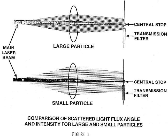
Low angle forward, light scattering, or more specifically Fraunhofer diffraction, is used to determine the size distribution of particles moving through a laser beam. When a small particle is illuminated by a coherent source of light, the angle of scatter is inversely proportional to its size, while the quantity of light scattered is directly proportioned, to particle diameter squared. These relationships are illustrated in Figure 1. To assure that only the scattered light is measured, provision is made to exclude the main laser beam after it passes the scattering region. The scattered light from large numbers of particles is selectively transmitted by a specially-designed optical filter. The resultant light transmitted at various angles is sorted out and recombined mathematically to provide particle size distribution data on the sample under analysis.
Physical Configuration
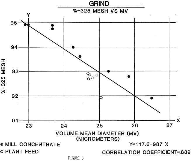
The MICROTRAC system is made up of 3 discreet sections: optics, electronics, and sample handling. The optics are best shown in Figure 2 as an exploded view of the entire optical path. A low-power helium-neon laser radiating at 0.6328 micrometer illuminates particles entrained in either a liquid or air flawing stream. Light is scattered by the particles, collected by a lens, and directed onto a computer-designed optical filter assembly. The MICROTRAC is a registered trade mark of Leeds & Northrup Co., a unit of General Signal optical filter transmits the various components of the scattered light to a photodetector, the output of which is digitized and directed to the electronics section.
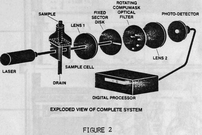
Electronic functions consist of the digitization of the photodetector output current by an analog-to-digital converter (ADC), and subsequent manipulation of accumulated data by the central processing unit (CPU) under instructions from the program (PRCM) section. Figure 3 shows schematically the data flew through the various circuit elements resulting in the computed particle size distribution which is displayed on a digital printer.
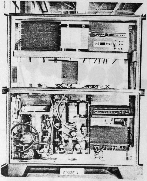
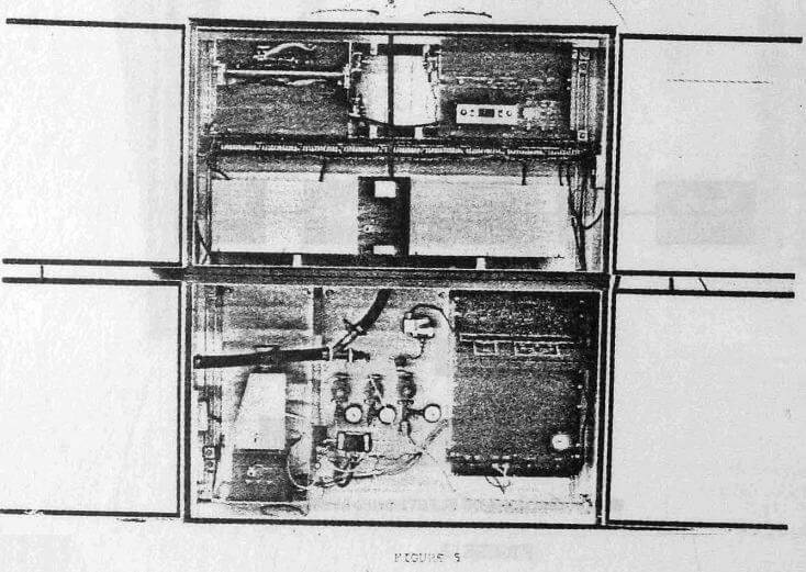
The liquid sample handling section is a recirculating sample carrier system made up of appropriate plumbing, a circulator pump, and a mixing chamber into which the sample to be analyzed is placed. The recirculating action allows particles to be carried to the sensing zone by a transparent liquid (usually water) and returned to the chamber where the sample is continuously agitated to insure delivery of a representative sample to the measurement region. When measuring dry particulate material they are transported using air aspirators to the analyzer region and removed by vacuum sources.
Microtrac Analyzer
The foregoing configuration of an instrument was first embodied as a laboratory analyzer. A large number of these analyzers are in use in quality control or production labs. When analyzing samples with the lab instrument, an operator deposits the sample into the mixing chamber, and allows the instrument to perform its computations and displays the results on a printer tape. The operator then flushes and rinses the mixing chamber to prepare for the next sample.
 |
 |
 |
 |
 |
 |
 |
 |
Related: 7 Best Laser Engraving Machines