What if the shaft were much larger, say, 300 m in diameter, or 3000 m, is the above approach to aquifer depressurization still valid? Is it feasible and practical to use wells to reduce the water inflow to a deep mine? If so, can the evaluation approach used in this paper be utilized? I believe the answers to the last two questions are yes, and yes, respectively.
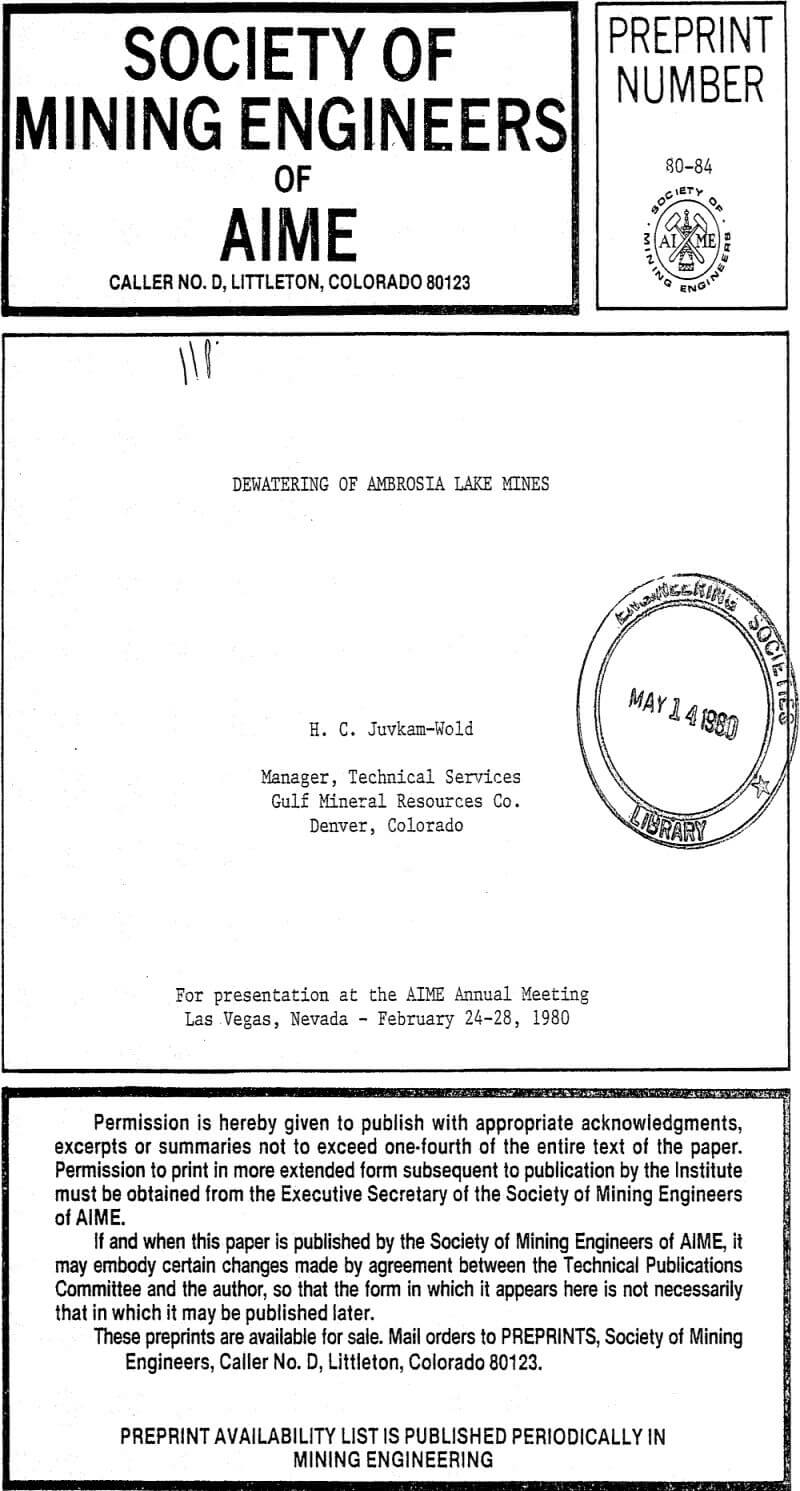
How many wells do we need? Where should they be located? Figure 10 shows the theoretical effectiveness of such a system. For simplicity of calculation it is assumed that the mine is of circular geometry, and is surrounded by a ring of uniformly spaced wells. The performance of such a system is evaluated on the basis of the reduction in flow rate to the mine, and is plotted in Figure 10 as the ratio of flow to the mine with the dewatering wells operating to the flow that would have been experienced in the absence of dewatering wells, expressed as a percentage. The upper curve considers the flow to a circular mine of 3000 m (1.9 miles) diameter. It is predicted that 11 wells would cut the flow to the mine in half, and 21 wells would cut it to one-third- the optimum location for these wells would be approximately 6000 m outside the center or the mine. It is assumed that the veils have been pumping for a period of two years.
The lower curve in Figure 19 predicts that, for a mine diameter of 300 m (one tenth the diameter and one hundredth the area of the mine considered in the upper curve) it would take six wells to cut the flow of the mine in half. With 26 wells the flow would be cut to about 15% of the value in the absence of wells. For this nine the optimum location of the wells was found to be about 1400 m from the center of the nine.
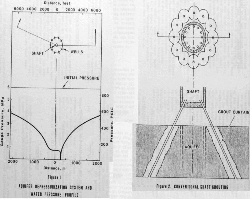
An aquifer depressurization system consists primarily of a number of wells surrounding a shaft, as shown in the upper half of Figure 1. Ideally the wells should penetrate the aquifer completely, and a submersible pump should be located below the aquifer if maximum drawdown is to be achieved. A downhole pressure gauge is useful for monitoring the water level in each of the wells. On the surface a power distribution system and a water collection system are installed. The system shown in Figure 1 consists of 10 wells located on the circumference of a circle with a 270 m radius with the shaft at the center. A typical pressure profile in the aquifer is shown in the lower half of Figure 1. In this figure, the shaft has not yet penetrated the aquifer.
Figure 2 shows, for comparison purposes, how a grouting system might be used to reduce the water inflow to the shaft. Here the shaft is surrounded by a grout curtain or wall.
Well Locations
Where should the wells be located, in what configuration? An optimal configuration, in an aquifer with isotropic and homogeneous properties, appears to be the circular pattern shown in Figure 1. Slight deviations from this system will not have a significant influence on the effectiveness of the system. The primary advantage of a symmetric system is that all the wells will handle more or less the same quantities of water. That way only one size of pump and motor will be used thereby reducing requirements for standby equipment. If the aquifer transmissivity is highly anisotropic, the well pattern should be changed to an elliptical one.
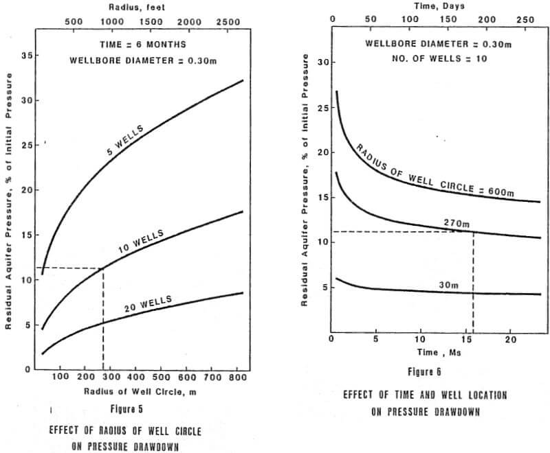
How far from the shaft should the wells be located? Figure 5 shows that the residual aquifer pressure increases as the wells are moved further away from the shaft. Hence, if minimum aquifer pressure is our goal, it would appear that the wells should be located as close to the shaft as possible. But what would happen when the shaft penetrates the aquifer, and the wells are located immediately outside the shaft perimeter? The “drawdown cone” from the shaft would instantly make the wells completely ineffective, and just about all the water that was initially flowing to the wells would now appear in the shaft. Clearly this is not a desirable situation.
When the interference effects between the shaft and the wells are considered, the minimum long term shaft water inflow rate for the “base case” system occurs when the wells are located about 18 m (60 ft.) from the center of the shaft (6 m diameter). But is this the optimum location? What, happens if the shaft is sinking through the aquifer, and a massive power failure shuts down all of the wells? How long will it take before the water inflow to the shaft starts to increase? How much time do we need before standby power can come on stream, and the wells can be restarted? Clearly, the answers to these questions should be considered in the context of each installation. Another question of relevance is how much development will take place in the aquifer, outside the shaft. For example, it may be necessary to receive support from the depressurizing wells while a pump station is being installed to handle the water.
In our case we decided that we did not want a power failure to affect the shaft (or mine) water inflow for at least one hour. This meant locating the wells at least 240 m from the shaft center. Because of surface topography and existing installations the well system was installed about 270 m from the midpoint between two shafts that are located about 125 m apart.
It is important to note that the water inflow rate to each well will increase as the radius of the well circle increases. For example, placing the wells 270 m outside the shaft results in an inflow rate about 40% higher than it would have been with the wells 30 m outside the shaft. Higher flow rates mean higher pumping costs, and may require larger diameter wells to accommodate larger pumps.