
Table of Contents
The Bureau of Mines has sponsored numerous high-risk research programs over the past decade to improve productivity and health and safety in underground coal mining by advancing state-of-the-art continuous face haulage systems, These systems are designed to move coal nonstop from the continuous miner to the next stage of rail or belt haulage (approximately 500 ft). One of the more innovative continuous face haulage systems is the monorail bridge conveyor (MBC). The MBC consists of a series of cascading belt conveyors supported by an inverted T-section monorail bolted to the mine roof. The basic concept was conceived and patented by the Bureau in 1979 (U.S. Pat. 4,157,757). It was designed and fabricated by the Goodman Conveyor Co., Inc. under a cost-sharing arrangement with the Bureau (contract J0333917). This system has the potential to improve productivity over conventional shuttle-car haulage systems by eliminating shuttle-car change, which can amount to 10 pct of the total face time for a continuous miner per shift; it provides a captive guidance system that requires only one operator, regardless of length; and it allows haulage in poor bottom conditions where conventional rubber tired and cat systems could not operate efficiently. Two of the MBC safety features are elimination of potential shuttle-car trailing cable and moving-vehicle accidents. MBC applications include all room-and-pillar operations such as driving rooms, entries and panels, pillar extraction, and shortwall mining.
Background
Underground continuous haulage systems have been employed in Europe and the United States since 1970. Commercially available systems can be grouped into three general categories: (1) crawler-mounted alternating series of mobile bridge carriers and piggyback bridge conveyors, and (2) monorail suspended systems, and (3) noncascading systems. The crawler-mounted systems generally require an operator every 50 ft and are limited to a total length of under 200 ft.
The only commercial monorail system available today has been installed in a U.S. trona mine and at several foreign locations. Although it has a unique continuous belt with no crossover points, it is relatively heavier and more expensive, and it is more difficult to change the system length in comparison with the MBC system, which can attain a length of more than 500 ft with just a single operator.
The noncascading systems, which have been recently introduced and remain untested underground, are relatively more expensive and present more difficulties in changing the system length.
Extensive surface testing and evaluation of the MBC was conducted by the Bureau. The objectives of the surface test and evaluation program were to—
- Rigorously test the MBC and improve performance, based upon observations made under simulated underground operation;
- Measure MBC performance criteria so that underground performance and operating requirements could be predicted;
- Determine if the MBC meets its design criteria and is worthy of an in-mine trial; and
- Prepare the MBC for an in-mine trial including electrical approval by the Mine Safety and Health Administration (MSHA).
The principal advantages of surface testing, prior to an in-mine trial, are that equipment performance can be proven, and improved upon, without interfering with production at an operating mine. This is absolutely paramount with face equipment such as the MBC. Even though the MBC has several potential advantages, most mines would not risk the installation and operation of unproven face equipment, since any failure would result in higher operating costs and lost production. Therefore, the mining industry tends to resist the introduction of novel mining systems if the in-mine trial does not meet anticipated short-term results. Even though the most rigorous surface test and evaluation program will not subject equipment to all of the harsh conditions found in underground mines, a surface test program does significantly increase the probability that the initial underground trial will be successful.
Surface testing of the MBC commenced in September 1982 and final modifications to prepare the MBC for in-mine use were completed in August 1985.
Description of Monorail Bridge Conveyor System
The MBC consists of a series of cascading belt conveyors suspended from special roof-supported monorail. The MBC-system specifications are shown in table 1.
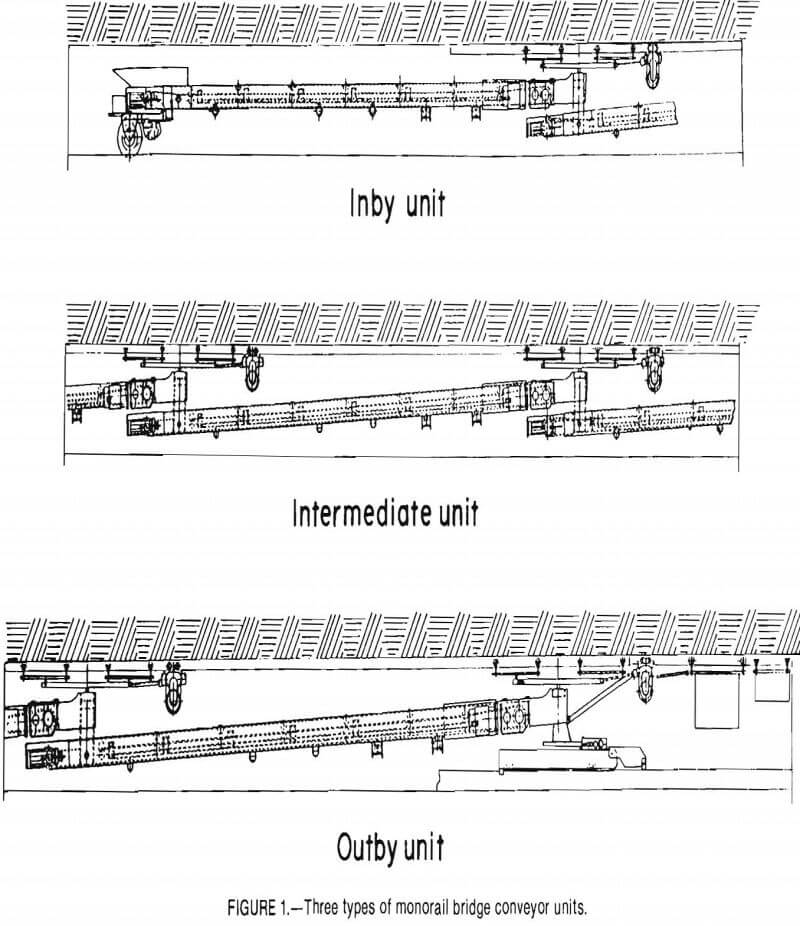
The three types of MBC units (inby, intermediate, and outby) are shown in figure 1. Each unit consists of a belt conveyor mounted on a rigid frame, monorail-suspension hardware, a monorail-mounted tram unit, and electric power and control components. All MBC units are totally monorail suspended except for the inby and outby units. The inby end of the inby unit is mounted on rubber tires, which are steered remotely. The outby end of the outby unit can be supported either by a dolly mounted on a rigid-belt structure or by monorail directly over the section belt. See table 1 for descriptions of various MBC components (including modifications made during the test program).
Conveyor Units
Individual conveyor units are fabricated from hollow structural tubing, providing a lightweight and rigid frame. Conveyor units are 27 ft, 7 in long overall, with an active length of 24 ft. Presently, 12 conveyor units are available for a system length of 288 ft;
Note.—All units can be controlled by single operator; helper optional. Safety features: Belt slip and sequence switches, disk brakes on each tram unit that engage automatically when tram power is shut off, emergency stop on each unit, pendant control from any unit, end-of-monorail stop on inby unit, and warning horn before belt startup.
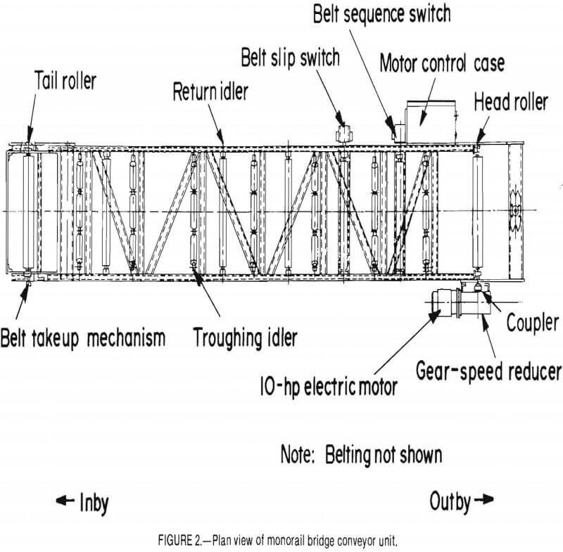
however, with electrical modification, additional units can be added to provide increased system length. A plan view of a typical intermediate unit is shown in figure 2. A 36-in-wide, 5/16-in-thick belt is supported on a conveyor unit with a maximum width of 7 ft. Catenary-type, 4-in-diam carrier idlers are installed on a 25° troughing angle. A 1,750-r/min, 10-hp electric motor powers the belt on each unit. A 7:1 double-reduction gear-speed reducer is coupled to the head-drive roller to provide a constant 400- ft/min belt speed, and 7-in-diam crowned drive and idler rollers are used. The tail idler roller is mounted on an adjustable screw-type takeup. The belt has a rated capacity of 600 st/h. Compression-spring belt cleaners are mounted under the head roller of each unit.
Power and Control
The MBC is operated by 460-V ac, three- phase, 60-Hz electric power provided by a No. 2/0 trailing cable to the outby main breaker box. Transformers located in each motor control box supply 120-V ac, single-phase, 60-Hz power for the control system. The 10-hp, 440-V ac, single-speed conveyor motors and the 1½-hp, 440-V ac, single-speed, reversing tram motors have across-the-line starting. The motor control box on each unit is equipped with an emergency-stop pushbutton station that disengages the main circuit breaker.
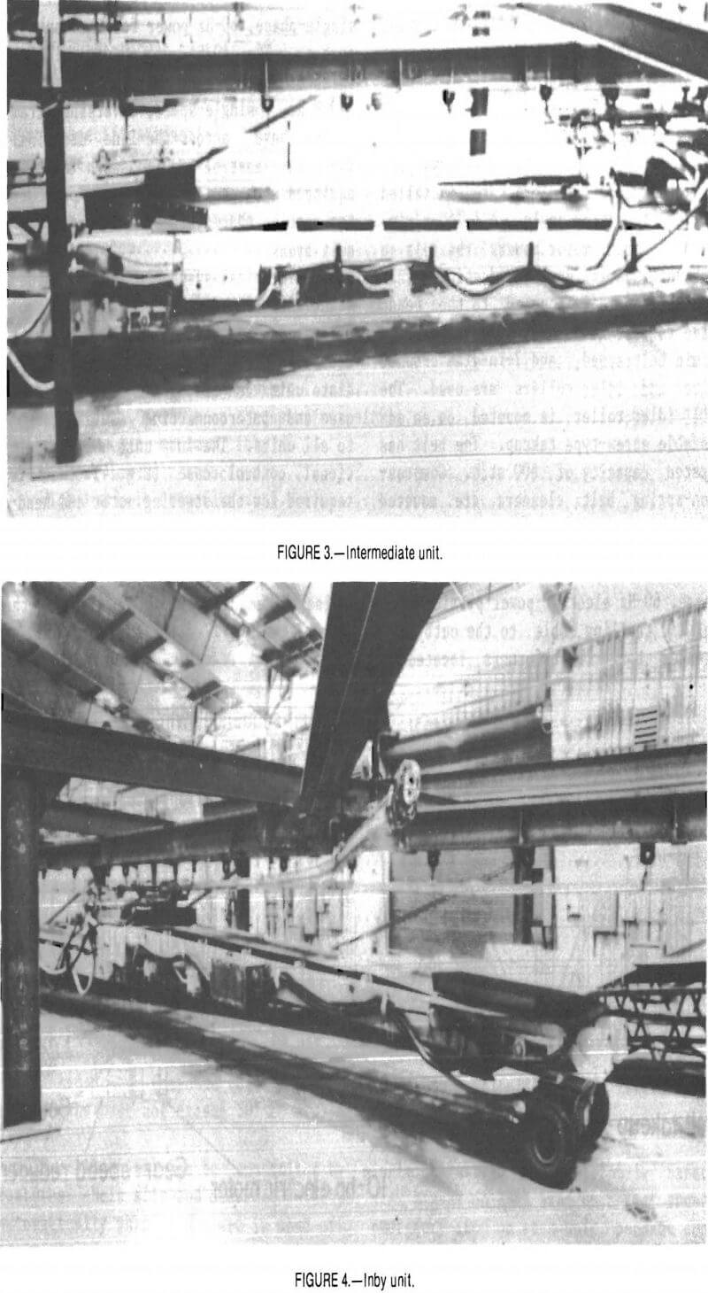
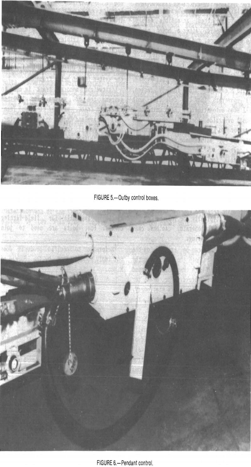
The electrical system is modular in design with identical power and control wiring on all but the inby and outby units. Figure 3 shows a typical intermediate unit containing the motor control case and interconnecting cables common to all units. The inby unit has an additional control case (fig. 4) that is required for the steering motor and headlight controls. The outby unit is connected to two additional control cases (fig. 5): the main breaker case, which houses the main-system circuit breaker, and the master control case, which contains the emergency-stop controls for the entire system.
The MBC system employs automatic sequential belt startup. When the conveyor is first activated, an audible warning signal is heard. After a brief period the signal stops, and the conveyors start in sequence beginning with the outby unit. Sequence switches allow each successive unit to start only after the preceding unit is running at full speed. Should a conveyor stop for any reason, all conveyors inby the defective unit will stop automatically. Each unit has a manual ovverride that will operate the conveyor on that unit. This control is intended for maintenance and diagnostic use only.
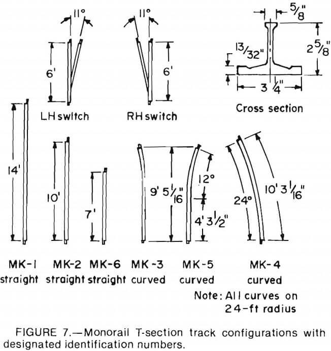
Controls for steering, tramming, and conveying are located on an umbilical pendant control. The pendant control (fig. 6) may be connected to any unit in the system. This provides operator convenience and allows positioning to avoid blind or unsafe MBC operation locations. During face operations, the pendant control will typically be located on the inby unit, so the operator can best control the inby steering.
The MBC system can be trammed on the monorail track in both the inby and outby directions, with each tram motor equipped with an electric brake. The brake remains set when the machine is stationary. Upon activation of the tram control, the brake releases and sets again when the tram control is deactivated. If a brake becomes overheated, it can be manually released to prevent further heat buildup.
Should any unit develop a major malfunction requiring it to be removed from the system, all electrical connections can be disconnected at the plugs and receptacles that interconnect the units. The units are reconnected in the same manner.
Tramming and Support System
Both ends of each conveyor unit are supported by eight-wheel carrier assemblies that distribute the weight of each conveyor on the monorail track. The carriers are designed to follow both vertical and horizontal curves in monorail track without affecting conveyor suspension. A 1,100-r/min, 440-V ac, 1.5-hp traction motor is used for tramming each conveyor unit. The motor drives two rubber wheels that are held against the underside of the monorail track. A 24:1 triple-reduction speed reducer is used to provide a constant tramming speed of 60 ft/min. Disk brakes on each tram motor automatically engage when the system is not being trammed.
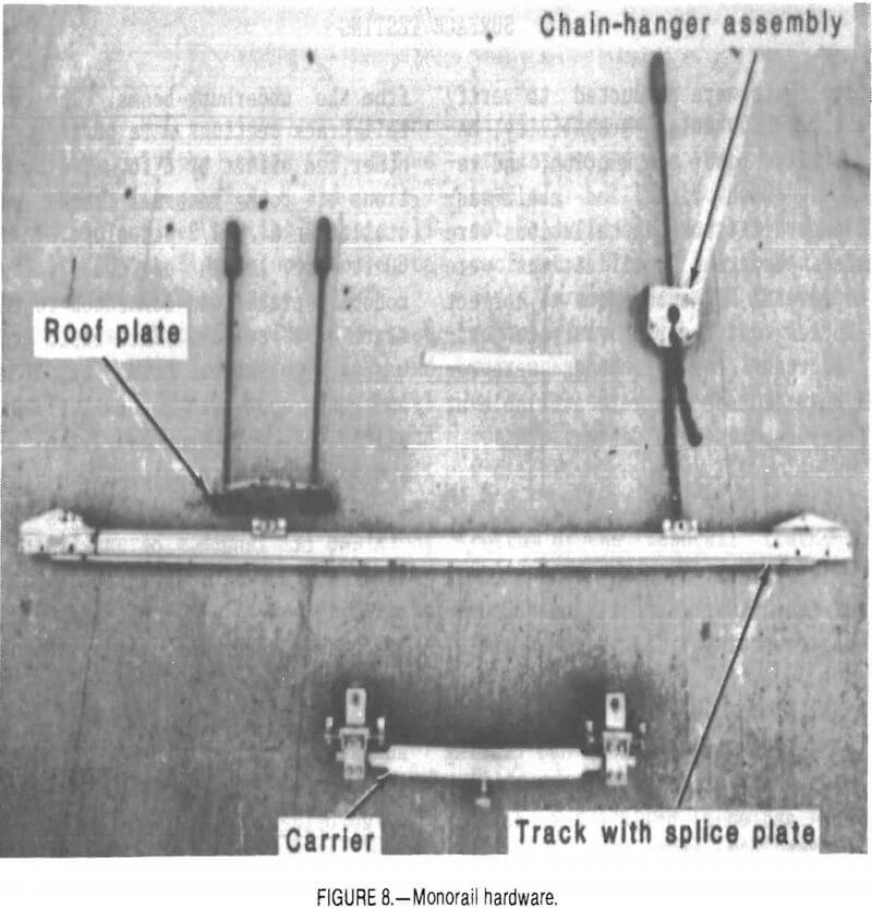
Lightweight monorail track is used to suspend the MBC system. The inverted T-section track, made by Cleveland Tram-rail (Cleveland Crane and Engineering, Div. of McNeil Corp., Wickliffe, OH)4 weighs 7 lb/ft and comes in eight factory-available configurations, as illustrated in figure 7. Straight rail Is available In 14-, 10-, and 7-ft lengths. Curved and combination rails in various lengths make 60° turnouts with a 24-ft radius. Other lengths and configurations of monorail can be fabricated underground to suit particular mine conditions. A hydraulic rail bender is commercially available for field-fitting curves. Four bolts are used to join
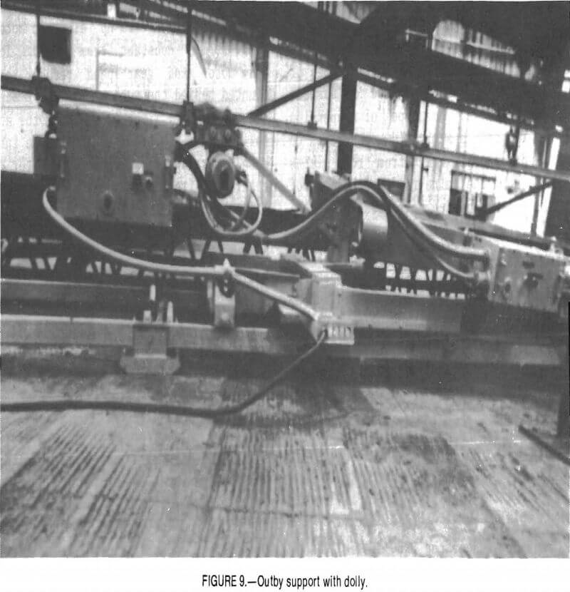
monorail track at overlapping splice plates. Both right- and left-hand manually operated monorail switches are available. Figure 8 shows two types of hardware that can be used to suspend monorail track. One type of suspension hardware uses a semi-rigid connection to suspend monorail track from roof plates attached to the mine roof with two roof bolts. Bevel-headed bolts seated in the roof plates are connected to the monorail track, allowing limited horizontal track movement. A second type of suspension hardware enables a nonrigid connection to suspend the monorail track using a chain-hanger bracket attached to the mine roof with one roof bolt. Varying lengths of chain connect the monorail track to the chain-hanger bracket, allowing horizontal and vertical movement of the monorail track.
Inby Support
The inby end of the MBC system is supported by two 9-in-wide rubber tires installed on 38-in centers. The wheels are powered by a 1.5-hp electric motor at 60-ft/min constant tram speed. The tram motor and gear-speed reducer are mounted behind the rubber wheels. A separate 440-V ac, 1.5-hp electric motor and ball thread are used to steer the inby wheel carriage. The steering motor is controlled from the pendant control.
The height of the inby conveyor unit over the rubber tires is 32 in. The height was increased to 40 in with the addition of a low-profile hopper.
Outby Support
In low-coal applications, the monorail track can be offset from the panel belt, and the outby end of the MBC can be supported by a dolly mounted on rigid belt structure (fig. 9) or on a chain panline. The dolly ensures transfer onto the panel belt without spillage. In higher coal, the outby end of the MBC could be suspended from monorail installed directly over the panel belt.
Surface Testing
Surface tests were conducted to verify and measure MBC haulage capability, maneuverability, power consumption, and reliability. Both rigid- and chain-suspended monorail track installations were evaluated. Numerous modifications were made to several MBC subsystems to correct deficiencies noted during surface testing. Important test sequences were recorded on videotape and are available at the Pittsburgh Research Center.
Test Rig Installation
A steel structure was constructed at the test facility to support the MBC during surface testing. This test rig (fig. 10) functioned as a false mine roof and was required to suspend the monorail track. The test rig enabled MBC testing on straight and radius tracks, through switches, and on a 6½-pct grade. It consisted of nine arches that supported underhung beams. Two separate 140-ft lengths of monorail track were supported from the underhung beams. The two monorail track sections were parallel to each other and offset by 8 ft. Two 80-ft portions of both monorail tracks were installed on a 6½-pct slope. A single, 60-ft arc length of the 24-ft~radius monorail track was connected to the main track by a switch. This basic test rig was used to support both rigidly bolted and chain-suspended monorail tracks. For initial test sequences, the monorail track was bolted to roof plates that were rigidly bolted to the underhung beams.
A 140 ft length of auxiliary belt structure was installed under one of the monorail tracks. The belt structure supported a 48-in-wide conventional belt that operated at 625 ft/min and was powered by a 50-hp electric motor. This auxiliary belt was used during closed- loop coal conveying tests. A beltscale weigh bridge was installed in this auxiliary belt to measure the MBC haulage rate.
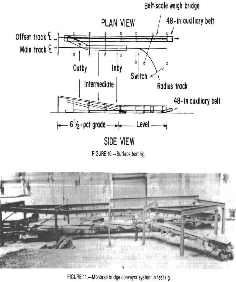
Although the MBC consists of 12 conveyor units, only the three (3) unique units (inby, intermediate, and outby) were used for surface testing because all potential MBC configurations could be represented using these three units.
The MBC was installed into the test rig using a chain hoist, forklift, and mobile crane. First, the eight-wheel carrier components were lifted by hand and threaded onto an open end of monorail track. Next, the tram units and suspension frames were moved into position, aided by a 1½-st chain hoist. Conveyor units were then moved under the suspension frames by forklift and picked up by the mobile crane and pinned to the suspension frame. Figure 11 shows the MBC units installed in the test rig. For initial test sequences, the outby end of the outby carrier was installed on the offset monorail track over the auxiliary belt, and the remaining carriers were installed on the main track. No difficulties were encountered during installation of the MBC units into the test rig. Although equipment that would not be available underground was used, a roof-mounted chain hoist and a scoop car could perform the same functions as the crane and forklift. After the conveyors were suspended, power and control cables were installed, and proper tram and conveyor-motor electrical operation was verified. Tram drive wheels were then adjusted to proper tension against the bottom of the monorail track, conveyor belts were adjusted to track in the center of the idlers, and test personnel were trained in proper operation.
Initial Checkout
After proper MBC operation was verified, preliminary tramming and conveyor function tests were performed. The MBC was trammed through the test rig and into the switch several times. The system was able to tram upgrade, downgrade, and through the switch without difficulty. Several modifications were necessary before coal handling was possible. The power and control cables were shortened to proper lengths, because excess weight had caused the units to lean toward the cables. Spillage guards were added on all dump points. (Appendix A lists all modifications made during the test program.) After the modifications were completed, preliminary loading trials were conducted with all MBC units in straight alignment. The MBC was intermittently loaded into the inby MBC hopper by a slow discharge of coal from the 500-lb capacity bucket of a skid loader. It was then loaded for several minutes by an 8-st- capacity shuttle car dumping into the inby MBC hopper. No major operational problems were encountered with the MBC during these tests, and it was able to convey coal at normal haulage rates.
During the initial checkout, a decision was made to install an automatic steering control for the inby rubber wheels. The original manual steering wheel, located beside the inby hopper, was awkward to operate and potentially unsafe. New gearing, a mounting bracket, an electric motor, and a control switch were installed.
Power Consumption
Power-consumption trials were conducted to determine overall system electrical characteristics and to specifically investigate if the number of tram motors could be decreased without affecting system performance. Each MBC unit is equipped with one monorail tram drive. An additional rubber-wheel tram drive is used on the inby unit. The rubber-wheeled tram drive on the inby unit, located several inches off the ground, was determined to be in an undesirable location because of potential water damage and ground clearance problems. Therefore, it was desirable to eliminate this motor, but only if doing so would not overload the remaining motors. For the power-consumption trials, the number and location of the tram motors were varied for both loaded and unloaded conveyors, and for upgrade and downgrade gradients. The test variables and results of these trials are listed in table 2.
The power consumption of the MBC tram motors was monitored by utilizing a current transformer with a ratio of 150:5 on the A and C phase legs of the MBC power cable. The current transformers were connected to transducers, which provided a 0- to 10-V dc output for a 0- to 120-kW power span. The current transformers had a factory-stated accuracy of ±1 pct. The watt transducers had a stated accuracy of ±0.25 pct. All power-consumption data were recorded by an eight-channel strip-chart recorder. Channel calibration was performed before each test.
For each test, the power-consumption instrumentation and recorder were activated, and the MBC system was trammed through predetermined start and stop points. The floor area underneath the inby unit was cleaned so that the rolling resistance of the inby rubber wheel would not vary.
For all trials (table 2) except G, H, I, and J, the original roller chain drive on the inby rubber wheels was connected. (This original roller chain drive was later replaced with a sealed, gear-speed-reducer driver.) For the trials using three rail motors (E, F, G, H, I, and J), the rubber-wheeled tram drive was electrically disconnected. For the trials using only two rail motors (S, T, V, W), only the monorail tram drives on the inby and outby units were operated, and the inby rubber-wheeled tram drive and intermediate unit monorail tram drive were electrically disconnected. For the trials using four rail motors (X, Y, Z, and AA), an additional tram motor was installed on the monorail immediately outby the inby unit tram motor. These two tram motors were connected by a short drawbar.
For trials A through 0 (table 2), the average power consumption for both level and 6½-pct-grade track was determined. The power consumption for a 20-ft length of track, at the start of upgrade trials and at the end of downgrade trials (fig. 11), was used for the level, kW on level track column of table 2. The power consumption for a 10-ft length of track, at the end of the upgrade trials and at
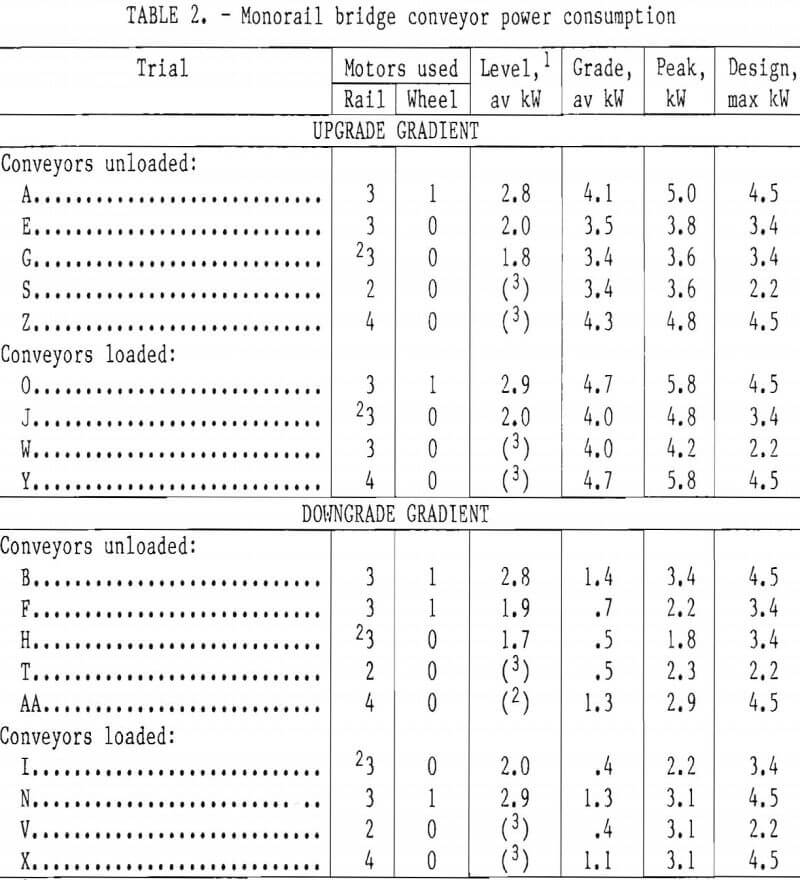
the beginning of the downgrade trials, was used for the “Grade, av kW” (6½- pct) column of table 2. Between these points, the grade traveled by each tram motor varied.
The strip-chart data were visually averaged for both the “level” and “grade” kilowatt values. The “Peak, kW” column of table 2 was taken as the maximum instantaneous power draw recorded by the strip chart for each trial (exclusive of starting power). The “Design, max kW” column of table 2 was obtained by multiplying the number of tram motors used and the nameplate horsepower rating by the conversion factor for horsepower and kilowatt.
For trials S through AA, only the average and peak power consumptions for the 6½-pct grade were determined, because the test-rig configuration did not allow the MBC system to tram on the entire level track section.
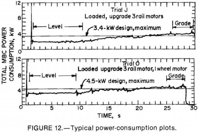
Figure 12 shows the strip-chart readouts from two typical trials. For trial J, three rail motors were used on the loaded MBC system, and the average power consumption while tramming up the grade was 18 pct over the design maximum power draw. For trial 0, three rail motors and the inby rubber-wheel tram drive were connected, and the average power consumption while tramming upgrade was 4 pct over the design maximum power draw. For both trials, power consumption while tramming on the level was below the design maximum. These data indicate that the inby rubber-wheel tram drive would be removed if the system normally operates on a level grade; however, tram-motor life would be shortened if the system must regularly tram upgrade.
Disabled Brake Test
The objective of the disabled brake test was to determine if the loaded MBC system would safely hold while stationary on the 6½-pct grade with a disabled brake. The loaded MBC system was trammed into the 6½-pct grade rack section, and the brake on the inby unit was electrically deactivated. The system remained stationary. Next, the inby and intermediate unit brakes were
deactivated, and the system remained stationary while being held only by the outby brake. The disabled brake test verified that the system can be safely operated on a grade, even if several brakes are temporarily disconnected.
Haulage Rate
The objective of the haulage-rate tests was to determine the maximum haulage capacity of the MBC units and to investigate spillage sources. To measure the instantaneous and total weights of coal moved by the MBC system, an electronic belt-scale system installed on the 48-in- wide auxiliary belt was used. To obtain a high haulage rate, the MBC system was installed In a closed-loop configuration (fig. 13). The MBC system was located in the radius portion of the test rig. The outby MBC unit dumped coal onto the auxiliary belt, which dumped onto a 30- ft-long, 36-in-wide flat belt. The flat belt then dumped coal into a shuttle car, which dumped back into the inby MBC unit hopper. Run-of-mine (ROM) bituminous
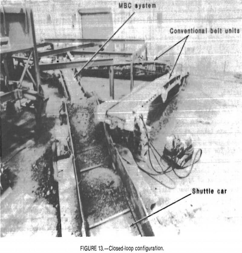
coal was added to the system by loading coal into the shuttle car.
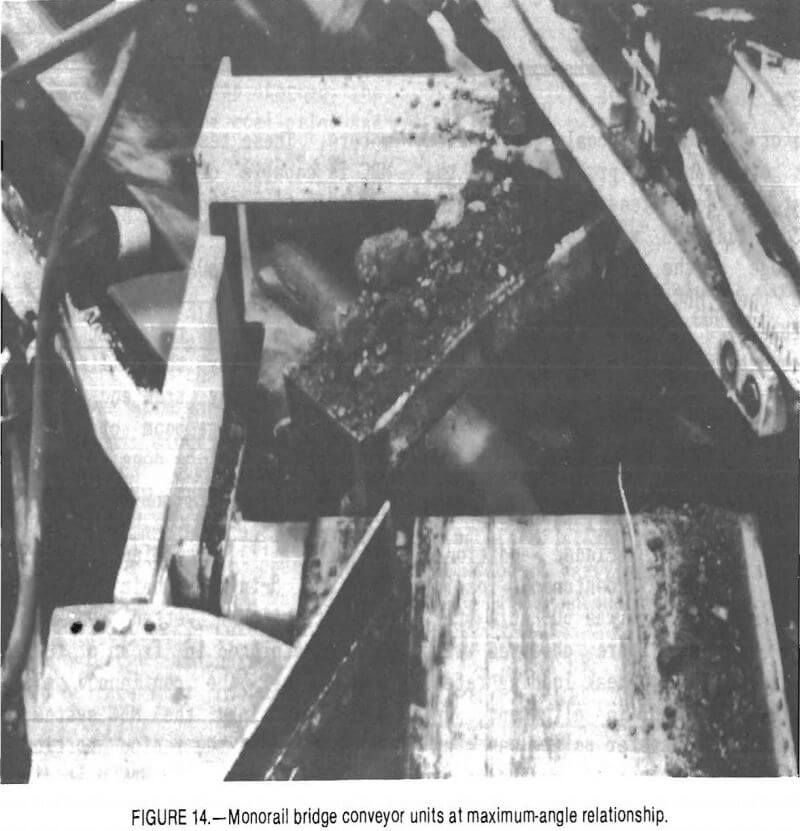
The MBC was located in the radius portion of the test rig so that the inby and intermediate MBC units were at a 43° angle to each other. This worst-case configuration (fig. 14) occurred where the two conveyors intersected at the center of the 60° arc of the radius track section.
During initial trials, belt-alignment problems were encountered on the intermediate unit. Prior to loading, the belts were adjusted at the takeup to track in the center of the rollers, but the belts untracked as soon as the belts were loaded. Belt-alignment problems were not encountered during the initial checkout haulage test when the MBC units were in straight alignment. It is assumed that the alignment problems were caused by side loading from the inby unit. With the inby and intermediate units installed at an angle, coal at the transfer point from the discharging conveyor had momentum perpendicular to the axis of the receiving conveyor. The belt would misalign in response to this side loading. Problems with coal discharging from the inby unit and hitting the suspension frame of the intermediate belt also contributed to the belt-alignment problem, since spillage was falling onto the return side of the intermediate unit belt and jamming the tail roller. Because of these belt-alignment problems, two modifications were made before further trials were attempted: (1) a 3/16— in/ft crown taper was put onto the head and tail rollers, and (2) the suspension frame was modified to provide more area for the coal to discharge. Crown taper is commonly used on belt conveyor rollers to improve tracking. Conveyor belts tend to move toward the direction of greatest tension, and the crown taper causes the conveyor-belt tension to be greatest at the center of the head and drive rollers, thus making the conveyor belt self-centered.
After the above modifications were completed, the haulage-rate trials were re-started. Figure 15 shows the strip-chart readout for the haulage-rate trial. An
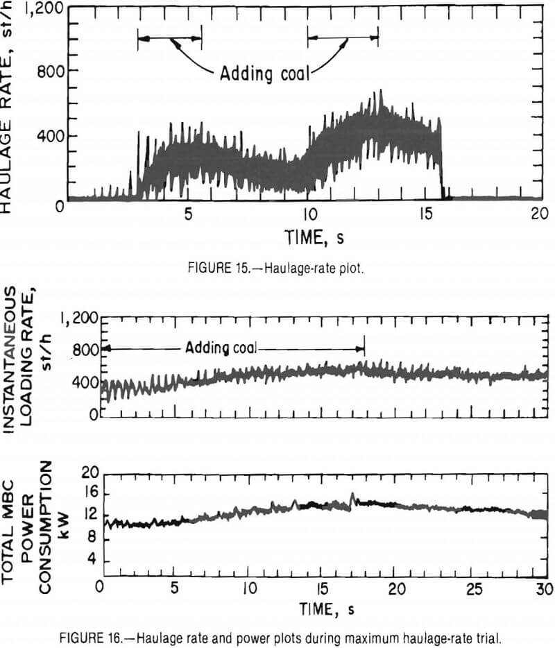
average of 450 st/h of coal was handled without experiencing problems with the MBC system. The decreasing haulage rate, after coal addition was stopped, was due to spillage at the shuttle car. Spillage at the MBC transfer points was negligible.
A second test was conducted to establish the maximum haulage rate of the MBC system. Belt-motor power consumption was monitored during this test, in addition to haulage rate. Coal was added to the closed-loop circuit until failure of the flat auxiliary belt precluded additional loading. The peak instantaneous loading rate during this trial was 600 st/h (fig. 16). No problems were observed with the MBC system during peak loading rates. All belts remained in alignment, and spillage at the transfer points was minimal. The maximum observed conveyor-motor power consumption was 16.8 kW for three motors. These tests verified that the MBC is capable of haulage at its design specification of 600 st/h.
Miner Loading Trials
The objective of the miner loading trials was to verify the ability of the MBC to simultaneously tram and receive coal from the discharge boom of a continuous miner, as would be done underground. A Joy 16CM continuous miner was used to load directly into the hopper of the inby unit (fig. 17). The miner had a 24-in- wide and 8-in-deep chain conveyor area. A 15-st pile of wetted ROM bituminous coal was placed in front of the continuous miner. The continuous miner was positioned inby the MBC system, which was located in the radius portion of the test rig. The outby MBC unit discharged onto the 48-in auxiliary belt. A 10-st
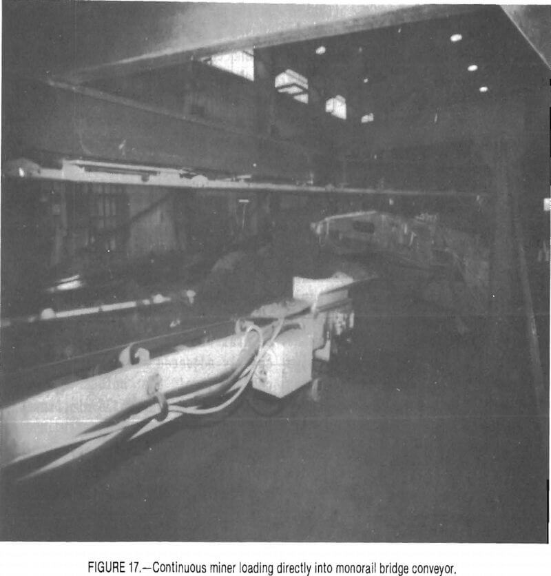
capacity shuttle car was used to receive coal discharged from the auxiliary belt.
For each trial, the instantaneous loading-rate instrumentation was started, the miner was trammed into the coal pile, and the miner operator directed the miner tail boom toward the MBC hopper. The MBC operator, located beside the inby MBC motor-control case, trammed and steered the MBC system as required to locate the MBC hopper under the discharge from the continuous miner. The miner advanced approximately 15 ft into the coal pile until the pile was eliminated. After each trial, the MBC and miner were backed up, and the shuttle car dumped the coal in front of the continuous miner. For several trials, the miner was maneuvered to simulate coal face cleanup operations. Total tonnage for each trial was determined from the belt-scale totalizer. The total tonnage loaded and maximum instantaneous MBC haulage rate for each trial were:
Trial A – 10.1 st loaded at a maximum rate of 690 st/h.
Trial B – 8.2 st loaded at a maximum rate of 720 st/h.
Trial C – 12.9 st at a maximum rate of 720 st/h.
Trial D – 10.0 st loaded at a maximum rate of 630 st/h.
Trial E – 7.6 st loaded at a maximum rate of 660 st/h.
The miner operator had no problems keeping the inby hopper of the MBC under the miner tail boom as the miner trammed into the coal pile. The MBC operator was also able to maneuver behind the mine during face cleanup operations. This test sequence verified the ability of the MBC to simultaneously convey coal and tram.
Reliability
To determine the reliability of the conveyor portion of the MBC system, the MBC was installed in a stationary closed-loop configuration. ROM bituminous coal was added to the circuit by slow discharges from a 500-lb capacity loader bucket into the hopper of the inby unit. Coal continued to be added until the belt-scale output showed an average rate of 500 st/h. Recharges of coal were occasionally necessary when spillage losses in the circuit caused the rate to fall to 300 st/h. All coal was wetted prior to loading for dust control.
For the entire trial, the instantaneous loading rate, the 48-in auxiliary belt speed, the belt-scale load-cell output, and the total MBC power consumption were plotted on a strip-chart recorder. During the reliability trial, an event log was maintained. Event description, time, MBC conveyor hourmeter and totalizer readings were recorded for each test event. Water was applied to the underside of each MBC belt every hour to control dust generation.
During the reliability trial, the MBC conveyors loaded 2,141 st of ROM coal during 5.7 h, for an average loading rate of 375 st/h. Loading-rate peaks of 600 st/h occurred several times during the trial. One failure occurred at 1.3 h into the trial: The conveyor drive coupler on the inby MBC unit came apart while the system was hauling at 400 st/h. To repair the coupler, the conveyor drive assembly was realigned with respect to the head drive shaft, and the coupler was replaced. The repair was accomplished by two mechanics in approximately 2 h. One adjustment was necessary at 4.1 h into the trial because it was observed that the outby unit belt was misaligned by several inches. The belt takeup was quickly adjusted without interfering with coal haulage.
Figure 18 shows two 36-min, instantaneous loading rate, and total MBC power-consumption traces. The upper trace occurred at 3.1 h into the trial. After coal addition stopped, the average loading rate was approximately 390 st/h. The average power consumption for the same
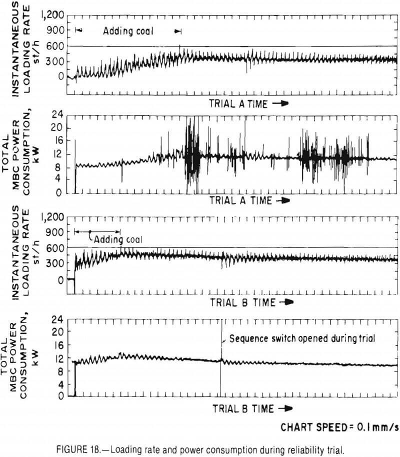
time was approximately 11 kW or approximately 15 hp; i.e., half the rated motor capacity of 30 hp. The scattered peaks and variations in power consumption were probably due to very fast openings and closings of one or more of the belt-slip centrifugal switches, which in turn shut the conveyor belt motors on and off. MBC belt-speed variations were not noticed during power-consumption variations.
The bottom trace was acquired at 4.1 h into the trial when the system was being restarted after a lunch break. After coal addition stopped, the average loading rate was 480 st/h. The average power consumption for the same time was 12.5 kW. Observed variations in both total MBC power consumption and loading rate were dampened with time because of more equal distribution of coal in the circuit. Midway through the bottom trace, a belt-slip switch was opened while the left was being cleaned. The belt cleaners at that time were tensioned against the return belt by a counter-weight of a lever arm. By pulling the lever arm, extra force could be applied to the belt cleaner. In this instance, extra force applied to the belt cleaner caused the return belt to raise and lose contact with the slip-switch roller. After these trials, the counterweighted belt cleaners were replaced with a compression-spring tensioner device.
The reliability trial was terminated at 5.7 h into the trial because of a spill at the intermediate discharge point that was caused by excessive coal flow, which buckled the hoop-type deflector. Coal was being added to the system at the time, and the haulage rate exceeded 600 st/h. This spill contributed greatly to the total spillage amount that had accumulated at the inby discharge point. After the trial, spillage at both the Inby and intermediate transfer points was raised. There was 700 lb of spillage under the inby transfer point, and 4,650 lb of spillage under the intermediate transfer point. Figure 19 shows the spillage under the inby transfer point. Prior to the spill, it was observed that spillage under the intermediate transfer point was twice the amount under the inby transfer
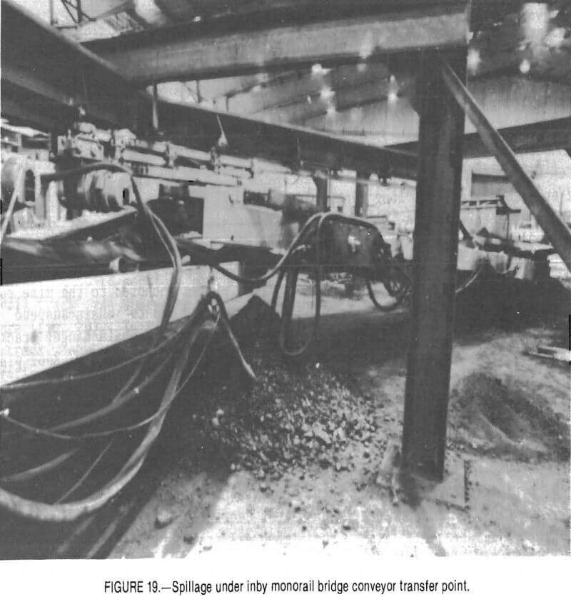
point, or approximately 1,400 lb. Based on the lower prespill assumed value, 2,100 lb of spillage occurred during the trial, and the total amount of coal loaded was 2,141 st. Spillage rate during this trial can then be computed as 0.05 pct of throughput. It is likely that the spillage rate might be higher during in-mine operation., since the system would be occasionally tramming during conveying operations. During the entire reliability trial, the inby and intermediate conveyors were at a 5° angle to each other, and the intermediate and outby conveyors were at 20° angles. During previous trials. It was observed that the amount of spillage at transfer points increased rapidly as the angle between the conveyor increased. After the tests, the center of the hoop-type deflector was bolted to the suspension frame to prevent future buckling.
System Compatibility with Low-Belt Structure
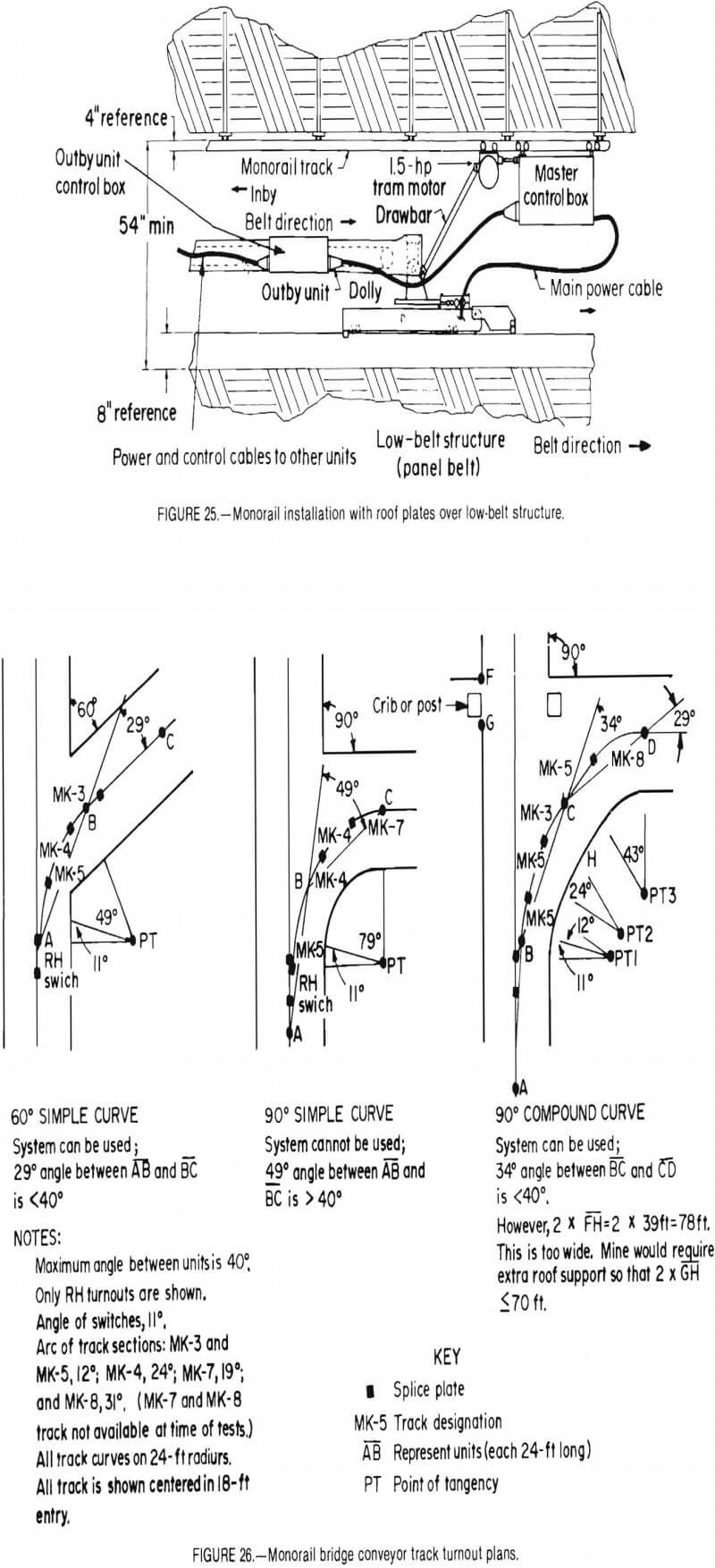
There are several ways that the outby end of the MBC can be located to ensure smooth coal transfer onto the section belt: One way is to suspend the outby unit from the monorail installed directly over the section belt, and another is to attach the outby end of the outby unit to a dolly supported by a low-belt structure.
To demonstrate the compatibility of the MBC system with a commercially available low-belt structure, a 32-ft-long section of low-belt structure and a dolly were installed under the chain-suspended right monorail track (fig. 9). The frame of the low-belt structure, designed for use with a 42-in-wide belt, was made of interlocking roller assemblies and connecting members. The low-belt structure was extended to a total length of 32 ft by the addition of framework made of 5½— in-wide channel sections. Rollers on the bottom and cams on the side of the mating dolly allowed easy mobility on the frame of the low-belt structure. The low-belt dolly was modified by adding an attachment bracket. This bracket firmly attached the outby MBC unit to the low-belt dolly, while permitting the outby unit to pivot in both horizontal and vertical directions. A 42-in-long drawbar was attached between the tram outby motor and dolly bracket. The main power cable to the MBC was then attached to the strain-relief clamp of the low-belt dolly, so that the power cable would always move with the system.
No problems were observed as the entire MBC system and dolly were repeatedly trammed along the 32-ft, low-belt structure in the inby and outby directions. The dolly moved smoothly on the low-belt structure; the only jerking motion occurred during starting and stopping because the outby tram motor was not rigidly attached to the outby MBC unit. When the system started tramming, force from the outby tram motor pushing against the drawbar tended to briefly lift the outby motor and suspended monorail track. However, steady-state tramming motion was quickly reached within 2 s because all tram motors were operated at the same speed.
The material-handling capability of the dolly-mounted MBC system was not tested. It is expected that transfer of material from the outby MBC unit to the panel belt would not be a problem in a dolly-mounted configuration, since the dolly fixes the outby unit at a constant height from the panel belt, and skirt boards can be added to the dolly as required.
Suspension of Monorail Track by Chain Hangers
There are several ways of installing special monorail track from the mine roof: One is to rigidly attach the track to roof plates anchored to the mine roof. Another method is to chain-suspend the monorail track from chain-hanger brackets anchored to the mine roof. Roof plates minimize the head room required for suspension hardware, but they are difficult to adjust and require two roof bolts. Chain hangers allow easy height adjustment and require only one roof bolt, but require extra head room. Initial test sequences were performed with the monorail track rigidly attached to roof plates. To determine If the MBC system could tram on freely suspended monorail
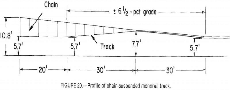
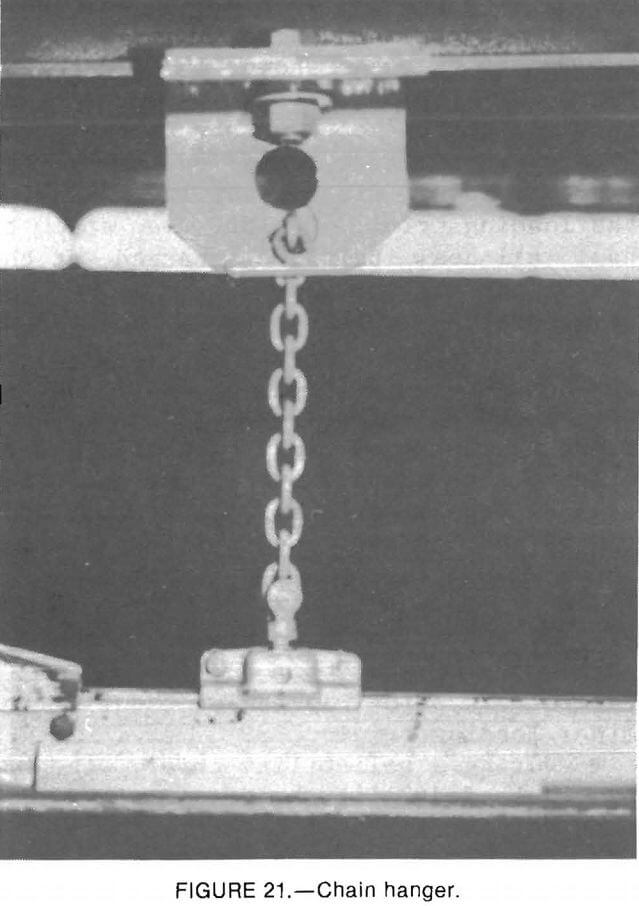
rail track, a 50-ft section of the right monorail track was suspended from chain hangers (fig. 20). To suspend the monorail track, chain-hanger assemblies, using various-length, ¼-in high-strength alloy steel chain with attachment hardware, were hung from the roof-bolt mounting plates on 4-ft centers. Each chain was held to the simulated mine roof by a chain-hanger bracket, which permitted adjustable chain height. The chain was connected to the top of the monorail track by a ½-in hex bolt welded to a chain clevis (fig. 21).
A hydraulically powered rail bender was utilized to make concave and convex vertical curves in the inverted T-section monorail track. The rail bender was operated by clamping a section of monorail track between a load ram and two pivot points. The load ram was activated by means of a hydraulic handpump. By using a displacement indicator on the rail bender, specific angles could be. made in the track. The radius of the bend could be controlled by changing the distance between the load ram and pivot points. The rail bender was then used to install two convex bends of 3.7°, 32 in apart, on the first 7-ft-long monorail track section. This track section, previously on a 6½-pct upward grade, was bent to end with a 6½-pct downward grade. Additional track sections were then connected to give the track a straight 6½-pct downgrade. When the top of the track reached a height of 68 in from the ground, a single concave bend was made so that the end segment of the track was parallel to the ground. In all cases, each 7-ft-long track section was suspended from the support structure by chain hangers on 4-ft centers before the next track section was connected. After the entire 50-ft section of track was suspended, several of the chain-hanger lengths required adjustment to prevent slack in the hanger assembly. The height was adjusted by changing the chain link in the adjustable hanging bracket. To constrain sideways movement, ¼-in chain installed perpendicular to the monorail tracks was used at the outby end of the suspended monorail track.
After the 50-ft segment of monorail track was suspended, the outby end of the outby MBC unit was mounted on a low-belt dolly, as described in the previous section. The ability of the MBC system to tram on chain-suspended monorail track was then observed.
No problems were experienced as the dolly-mounted MBC system was repeatedly trammed in both the inby and outby directions on the chain-suspended monorail track. The eight-wheel carrier assemblies negotiated a 13-pct change in grade over a 3-ft distance without any noticeable binding. Sideways movement of the suspended monorail track was not observed.
System Compatibility with Hopper-Feeder
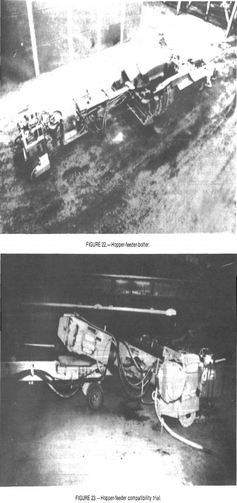
Although the inby MBC unit can be loaded directly by a continuous miner, in most cases, it would be desirable to include surge and breaker capabilities be¬tween the miner and the MBC. The Bureau has developed a separate prototype mining machine, the hopper-feeder-bolter (HFB), to perform that task. The HFB is a cat-mounted vehicle that includes a 5-st capacity surge hopper, an onboard lump breaker, a variable-angle discharge boom and an optional bolter-module (fig. 22) to permit bolting beside a two-pass continuous miner. This provides the advantage of eliminating face-to-face place changes during the mining cycle. The bolter module was removed and only the hopper-feeder (HF) was used during trials with the MBC.
To evaluate the ability of the HF to load the MBC, a compatibility trial was conducted. The HF was located inby the MBC, and the MBC was loaded with coal discharged from the HF. The low-profile hopper on the MBC was removed to enable the 16-in profile HF discharge boom to fit between the top of the inby MBC unit (32 in) and the underside of the monorail track (59 in). As shown in figure 23, there was little clearance between the HF boom and the top of the inby MBC unit and a very small target area on the MBC to permit loading without spillage. During the loading trial, the MBC was able to haul all coal being discharged at the maximum HF loading rate; however, excessive spillage was observed at the trans¬fer point between units. An improved interface between units would be required before they could be used together. Since the HF boom must clear the under¬side of the monorail track, the exact design of the interface will depend upon the height of the monorail installation at the mine site.
Summary of Surface Test Findings
Surface testing verified that the MBC system properly performs its design functions and is worthy of an in-mine trial. Highlights of the surface test program are summarized below.
- Tram-motor power consumption was measured for several tram-motor configurations.
- The braking system is more than adequate, as one functioning brake unit held three loaded MBC units on a 6½-pct grade.
- The ability to haul the design capacity of 600 st/h was verified.
- The MBC was capable of being loaded by a continuous miner, A maximum haulage rate of 720 st/h was measured during the miner loading trials.
- During a reliability trial, the MBC system loaded 2,141 st of coal in 5,7 h with only one minor coupler failure.
- The MBC was trammed with the outby end supported by a dolly mounted on a low-belt structure.
- The MBC was able to tram from monorail suspended from roof plates and chain hangers.
- The MBC is compatible with the HF, which provides surge capacity and lump-breaking capability inby the MBC. An improved interface between the MBC and HFB is required to suit mine conditions.
Modifications
Numerous modifications were made to the original system design to correct the problems observed during surface testing. A complete listing of modifications is contained in appendix A. Major modifications included.
- Conveyor belt head and tail rollers were crowned to improve belt tracking.
- The clearance area in suspension frames was increased to create more area for coal transfer between conveyors.
- Deflectors to direct coal flow and control spillage were installed at conveyor transfer points; belt cleaners were installed on the underside of each conveyor.
- Remote-controlled steering was installed.
- A limit switch to prevent the system from tramming at the end of the monorail was installed.
- A lightweight pendant control was installed.
- The wheel base of the inby wheels was increased for greater stability.
- The control circuitry was changed to utilize an intrinsically safe control pendant.
The review process for the MSHA experimental permit was initiated in December 1984. Review of the control circuitry revealed some problems. The system was designed with intrinsically safe control circuitry intermingled with 120-V ac power in a multiconductor control cable. To remedy this situation, 480- to 120-V ac transformers were installed into each motor control box and additional safe isolation relays were installed. The main contactor allowed 120-V ac power into each control box even when the main switch was in the “off” position; this was corrected by replacing the original contactor in the master control box with a circuit breaker located in a separate enclosure. The changes made to meet MSHA requirements are listed in appendix A.
Mining Plans
Based upon observations made during surface testing, the following mine re¬quirements are suggested:
- The minimum working height of the MBC is 48 in. The minimum working height increases to 54 in if the outby end of the MBC is supoprted by a 6-in high low-belt structure (figs. 24-25). Additional working clearance would ease cleanup under the MBC.
- Maximum gradability of the system is 6.5 pct without excessive tram motor wear. Greater grades can be negotiated at the expense of decreased tram-motor life.
- A minimum entry width of 14 ft is possible if 60° crosscuts are used and intersection corners are rounded; however, a wider entry is desirable to allow a walkway at all points on the clearance (right) side of the system.
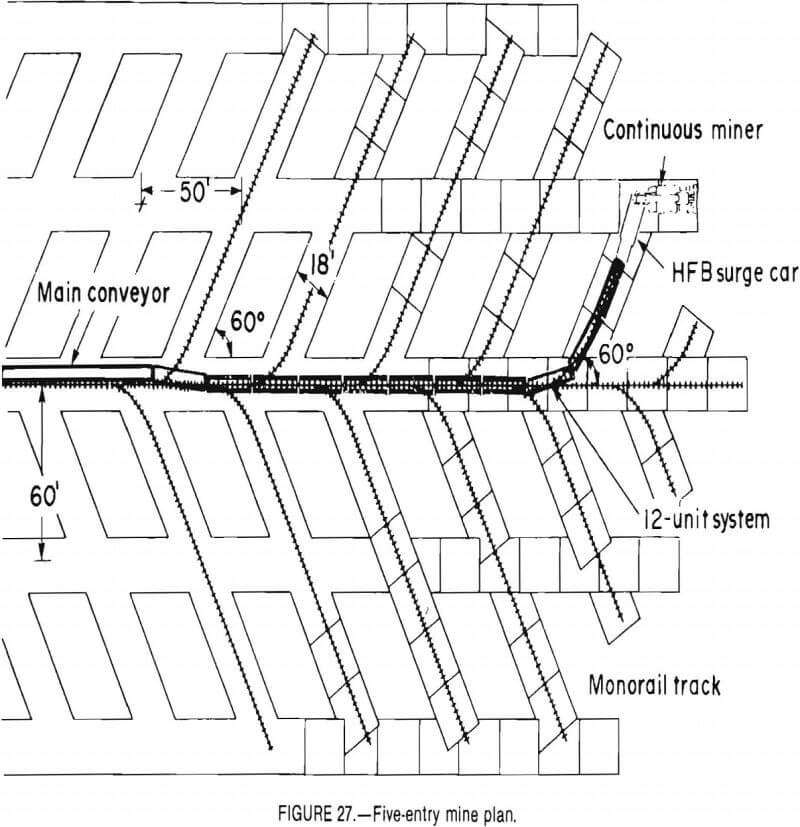
- The MBC was designed for 60° crosscuts using the 24-ft radius monorail track, however, crosscuts of 90° can be negotiated using a compound curve. In any turnout configuration, the angle between MBC units must be less than 34° to prevent unit-frame interference with each other. An advantage of 60° crosscuts is that spillage between units will be minimized because potential spillage at transfer points increases as the angle between units increases. Figure 26 shows track installation plans for both 60° and 90° crosscuts.
- Suporting the MBC system should not be a problem because the eight-wheel carriers distribute conveyor weight over a 6-ft length of monorail track, which results in a typical load on each suspension point of less than 1 st. Although not tested, resin bolts are recommended over mechanical bolts to better withstand tramming-induced vibration.
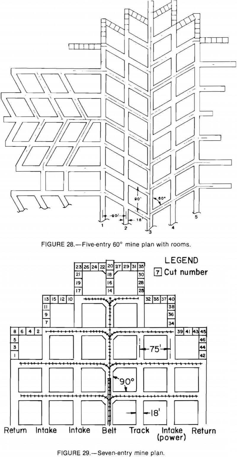
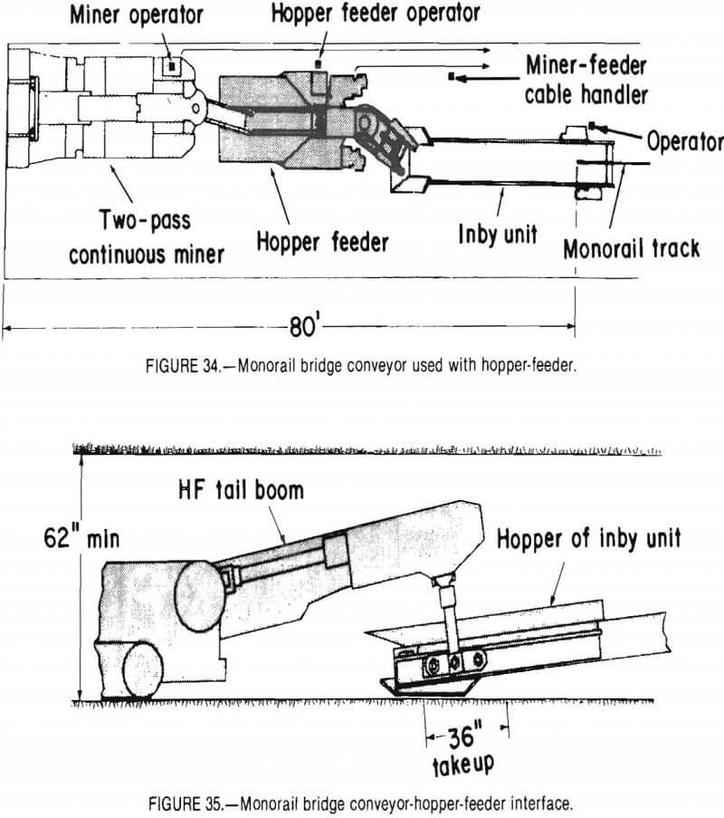
The MBC can be used for room-and-pillar mining (figs. 27-29), longwall development (fig. 30), or shortwall mining (fig. 31). For room-and-pillar mine plans, the monorail track does not have to be installed in all mine entries. As illustrated in figure 27, the monorail track would typically be installed over or beside the panel belt in the center entry and in each crosscut. The combined length of the inby MBC unit and the continuous miner enables mining in entries that do not have monorail track installed. The hopper of the inby MBC unit can be up to 20 ft from the last point of monorail suspension. Assuming that a typical continuous miner is 35 ft long, the continuous miner cutterhead can be up to 55 ft from the last point of monorail installation (fig. 32). Various cut plans are possible, depending on local conditions.
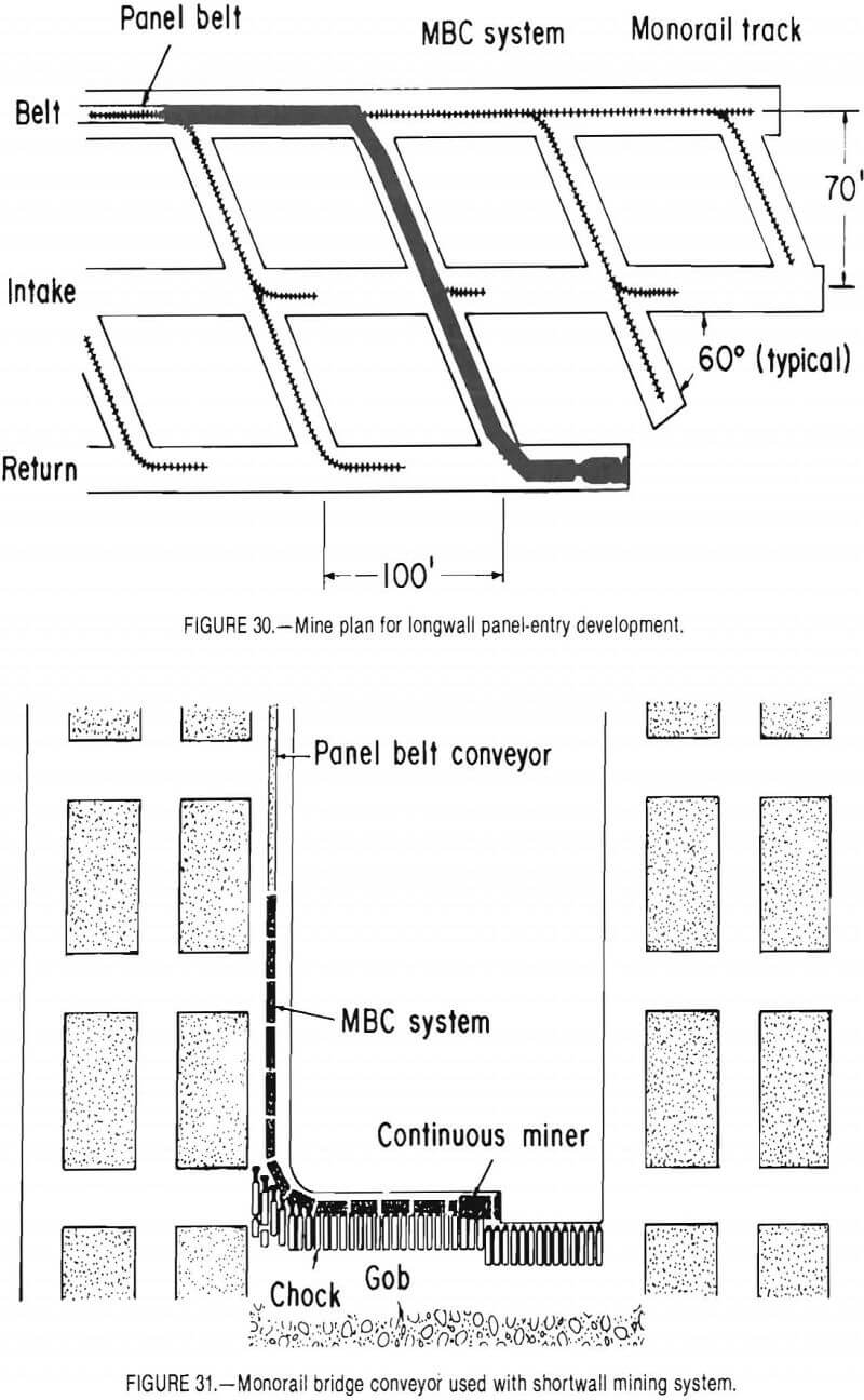
A potential application of the MBC system would be in longwall panel development. As shown in figure 30, the 288-ft MBC system would be of sufficient length to advance two crosscuts of a three-entry heading, thereby potentially reducing longwall-panel development time.
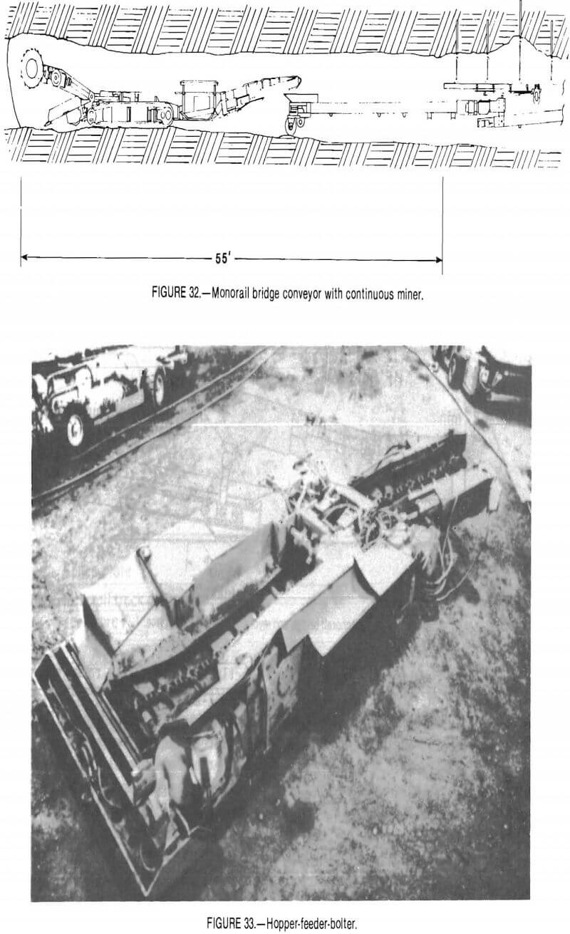
An alternate use of the MBC system would be to provide continuous haulage capability for shortwall mining sections. Shortwall mining has the potential to provide productivity advantages of longwall mining without high capital costs. A major impediment to more shortwall application is the lack of a continuous haulage system. As shown in figure 31, the MBC connects the continuous miner to the panel-belt conveyor with the monorail track bolted to mine roof in the headgate entry. In the face area, the monorail is supported underneath chocks with the provision that the lightweight monorail track could be manually connected after the chocks are advanced.
If oversize material (over 12 in) is regularly encountered during the mining cycle, a crusher should be used inby the MBC system to avoid clogging MBC transfer points. The previously described HFB with optional bolter removed, shown in figure 33, can perform that task. Additional advantages of using the HFB between the continuous miner and MBC are that (1) surge capacity is provided; (2) an outby feeder breaker can be eliminated; and (3) extra system reach is provided. As seen in figure 34, the continuous miner cutterhead can be up to 80 ft from the last point of monorail installation. If the MBC is used with the HFB, the two systems could be connected (fig. 35).
One operator is required for the entire MBC system, although it may be desirable to temporarily station a helper at the outby transfer point to the panel belt to assure proper transfer. Mine personnel should be instructed to stay on the clearance side of the system where the emergency shutoff switches are located.
In a continuous haulage mode with the MBC positioned directly behind the continuous miner, the MBC operator would control tramming and steering to follow the miner. The pendant remote control will allow the operator to be positioned to avoid pinch points and to view loading operations. Various hopper capacities and profiles could be installed on the inby end of the system to maximize the target area for the miner operator. Depending upon the mine plan, the miner power cable could be carried by the MBC.
Two methods of monorail track installation are possible. If lack of head room is a problem, the monorail track can be directly attached to the roof, using roof plates (fig. 25). Another method, using chain hangers, is shown in figure 24. Roof plates require two roof bolts for installation, while chain hangers require one. Chain hangers permit monorail installation in high and uneven roof conditions. Figure 8 shows the two types of installation hardware. The size and length of the roof bolt would depend upon local mine conditions. Roof bolts that are part of the roof-control plan cannot be used for monorail suspension. Suspension on 4-ft centers is recommended for straight track sections. Suspension on 3-ft centers is recommended for curved track sections.
Monorail track can be installed either on or off cycle with the cutting plan, depending on the mine and cut plan selected. Oncycle installation plans would require the roof-bolter crew to install monorail track in a cut immediately after the cut is bolted. Off-cycle
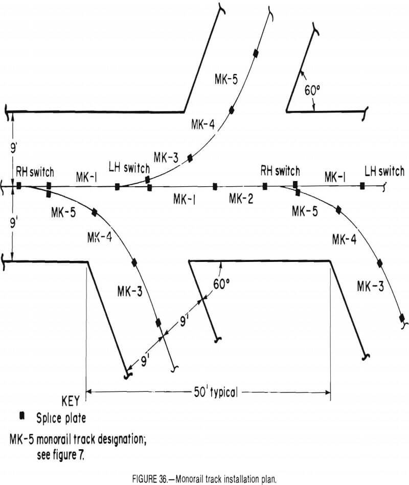
installation plans would allow monorail-track installation during an idle shift. Monorail-track layout must be consistent with as-cut mine geometry to ensure adequate clearance at turnouts. Figure 36 shows a typical track layout for 18-ft- wide entries and 60° crosscuts. The track should always be installed to maintain clearance for personnel at all points on the right side of the MBC.
Conclusions
The MBC system, which includes the HF as a beneficial option, is a prototype continuous face haulage system that has the potential to significantly increase productivity and offer additional safety. Extensive surface tests were conducted by the Bureau to evaluate equipment performance criteria and to identify and make necessary modifications before conducting an underground trial. Successful test results under simulated mine conditions indicate that this innovative haulage system offers the raining industry potential benefits for increased productivity, while providing increased personnel safety. Mining plans were developed that offer application of the MBC system for room-and-pillar, longwall development, and shortwall mining sections. A patent (U.S. Pat. 4,159,757) was granted to the Bureau in 1979 for the basic MBC concept. An in-mine trial is planned at a midwestern underground coal mine, using the MBC and HF as a continuous face haulage system.