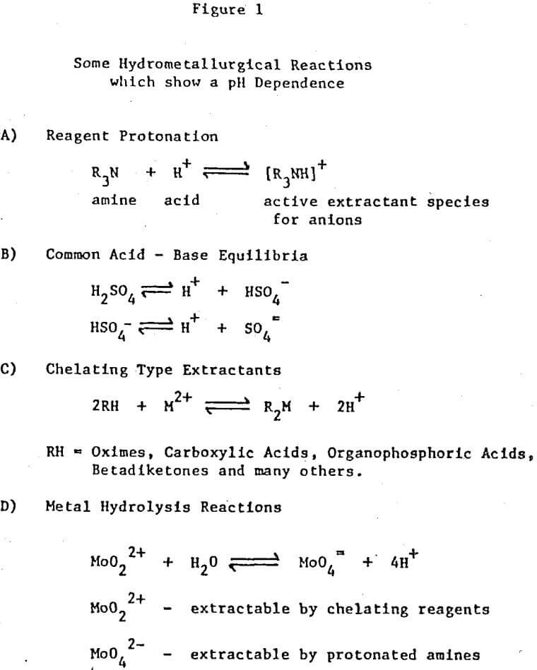
The control of pH in solvent extraction circuits is an old technique but one which has a large potential for future use. The equilibrium position of any reaction which has hydrogen or hydroxide ions, either as products or as reactants, can be controlled by pH adjustment. Several examples of reaction types which are important in solvent extraction systems and which also show a pH dependence are shown in Figure 1.
It is the intent of this paper to discuss pH controlled solvent extraction reactions for some relatively simple systems through more complex ones.
It is obvious that in order to control pH in a system there is needed a way to first measure the pH, and secondly, add the proper amount of acid or base. Fortunately pH control units are available which do both. The pH probe provides a signal to the pH controller which in turn activates a pump or control valve to meter acid or base into the system until such time that the desired pH is reached. The pH controller then shuts the addition mechanism off. The type we use in our laboratory (Chemtrix Model ASA) will provide ± .1 pH unit control provided some care is taken in setting the flow of the added stream. In many cases such close control is not necessary while in other cases it may be needed. Normally we insert our pH probe directly into the mixer and add acid or base directly to the stirring emulsion. This method gives the fastest response to changes in mixer pH and consequently we feel the best circuit control. Our pH probes limit us to controlling aqueous continuous emulsions but electrodes are available which will measure pH in an organic continuous emulsion. If tight circuit control is not needed the pH probe could be inserted in the settler or even in the aqueous overflow at the rear of the settler.
pH Controlled Extraction
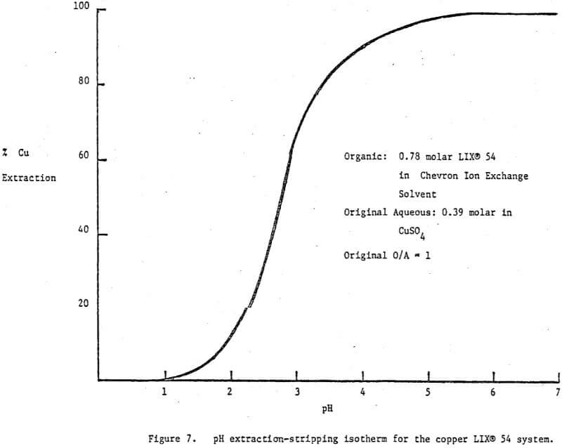
There is one circuit operating on a weakly acidic copper stream which deserved special mention. The stream contains 25 g/l Cu and greater than 20% (NH4)4SO4 at pH 1.6-1.8. The problem is to remove the copper for recycle while at the same time providing an exit stream below 10 ppm copper at a pH of 5.5 or greater. Since the pH of the existing stream must be adjusted up to 5.5 there is no need to use a strong copper extractant. In fact a weaker extractant with a high loading capacity is preferable. LIX 54, whose pH isotherm is shown in Figure 7, was recommended and is used at —80 v/v%. Note that at pH 5.5 the reagent is 100% loaded while at pH 1 it is 100% stripped. Observe also that the pH isotherm was run with relatively high reagent and copper concentrations, i.e., .8 molar and .4 molar respectively, making it directly applicable to the system under discussion.
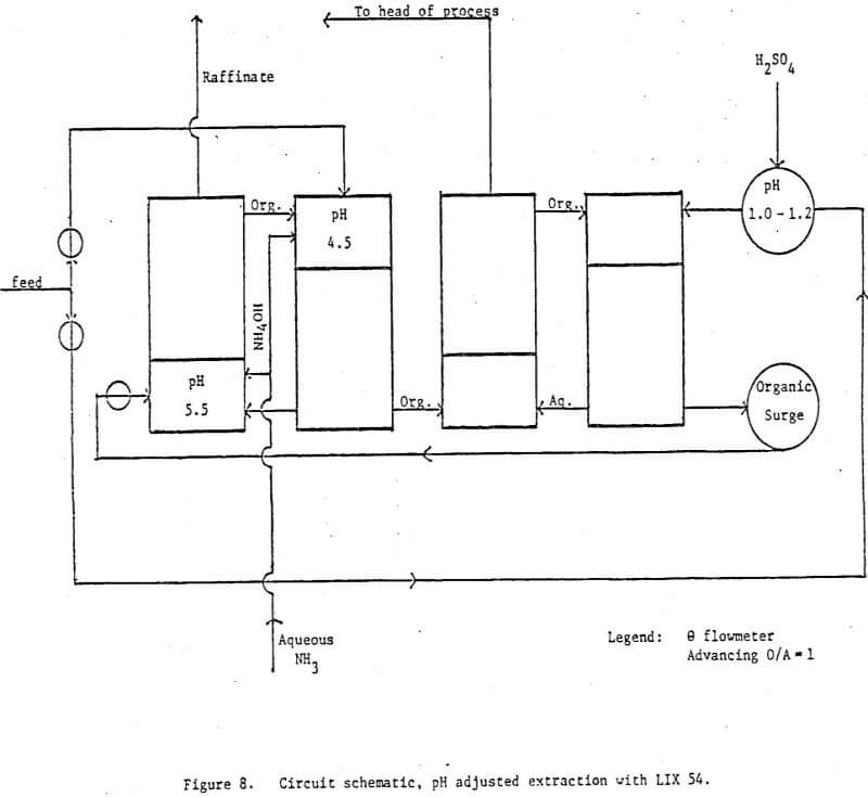
The circuit is shown in Figure 8. One half of the copper stream is taken to two countercurrent extraction stages whose mixers are pH controlled with aqueous ammonia at 4.5 for E1 and 5.5 for E2. The raffinate normally contains <10 ppm Cu, is at pH 5.5 and has a high enough (NH4)2SO4 content to make it suitable as a feedstock for use in the liquid fertilizer industry. The other half of the copper stream is pH adjusted to 1.0 – 1.2 with concentrated H2SO4 and is then used as the strippant for the loaded organic. Under these conditions 96-98% stripping is accomplished in two countercurrent stages. The spent stripping solution is recycled back to the head of the overall process while the organic is recycled to extraction. The plant manager says the circuit runs very smoothly and the pH controllers do a “beautiful job”. This circuit is important because it shows that exact pH control in extraction is feasible on a commercial scale.
A look at some of the circuit data generated is the best way to show the value of direct pH control in both scrub stages and selective stripping processes and also some of the problems with this type of circuit.
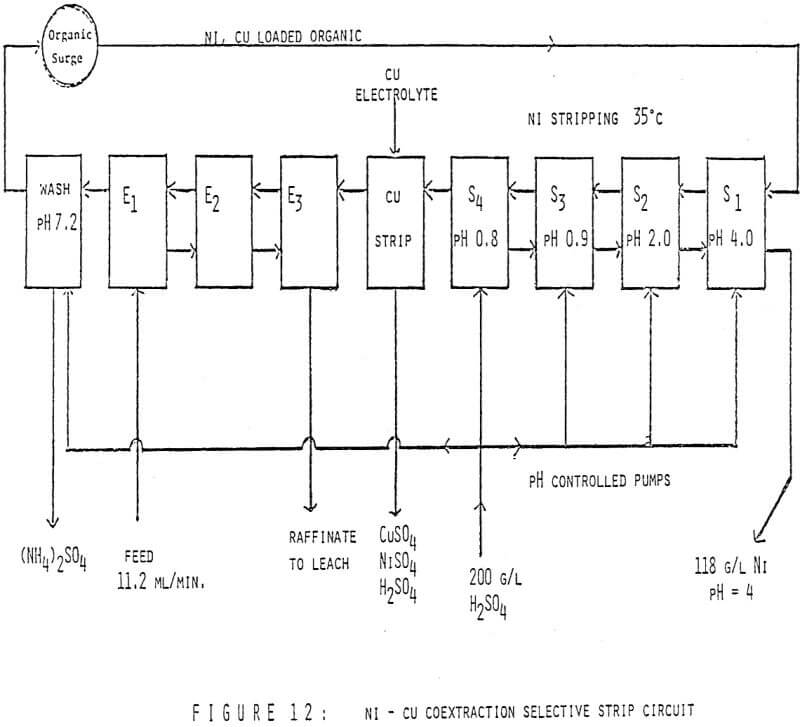
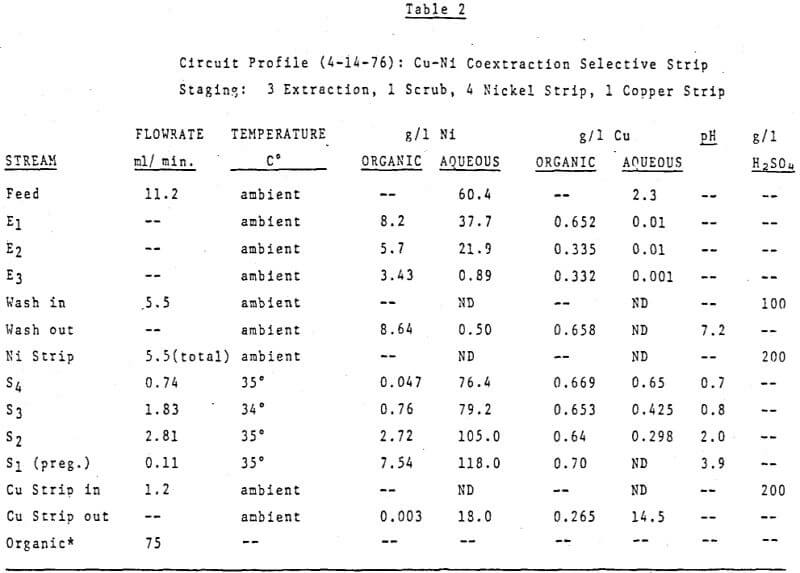
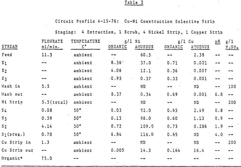
The first circuit was run on an ammonium sulfate leach solution containing 60 g/l Ni and 2.4 g/l Cu which was submitted to us for study. The organic was 40 v/v% LIX 64N in Kermac 470B. The circuit was initially set up with 3 extraction stages, 1 pH controlled wash stage, 3 pH controlled nickel stripping stages and 1 copper strip stage. The desired end results were simple – to make a metal free raffinate while at the same time producing a copper free nickel solution suitable for electrowinning. Thus the pH controllers were set at 7.0 in the wash stage and at 4.0, 1.7 and 1.7 in S1, S2, and S3 respectively. Then the circuit was started up, flowrates set and metal contents of various streams monitored. After a few days it was realized a longer retention time was needed in nickel stripping and a fourth pH controlled stage was added. The final circuit design is shown in Figure 12. Circuit profiles for the last two days of operation are shown in Tables 2 and 3.
Important things to note are:
- The consistently good nickel pregnant electrolyte produced (116-118 g/l Ni at a pH of 4.0 with no copper detectable by AA) while using 200 g/l H2SO4 as the strippant;
- The increased nickel stripping in and S2 at 50°C verses 35°C;
- The overall good metal recovery;
- Finally, particular attention should be paid to the Cu/Ni ratio of the copper strip solution verses that of the organic stream entering this stage.
Obviously the nickel content of the copper strip solution is much higher than would be predicted from the analysis of the nickel stripped organic stream. The explanation is simple, high quantities of nickel were carried into the copper strip stage before the fourth strip stage was added and the pH’s controlled at the final values. Since the copper strip solution advances at a very low flowrate the time required to attain equilibrium in this stage is much longer than the few days the final circuit design was run.
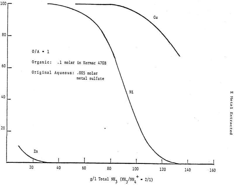
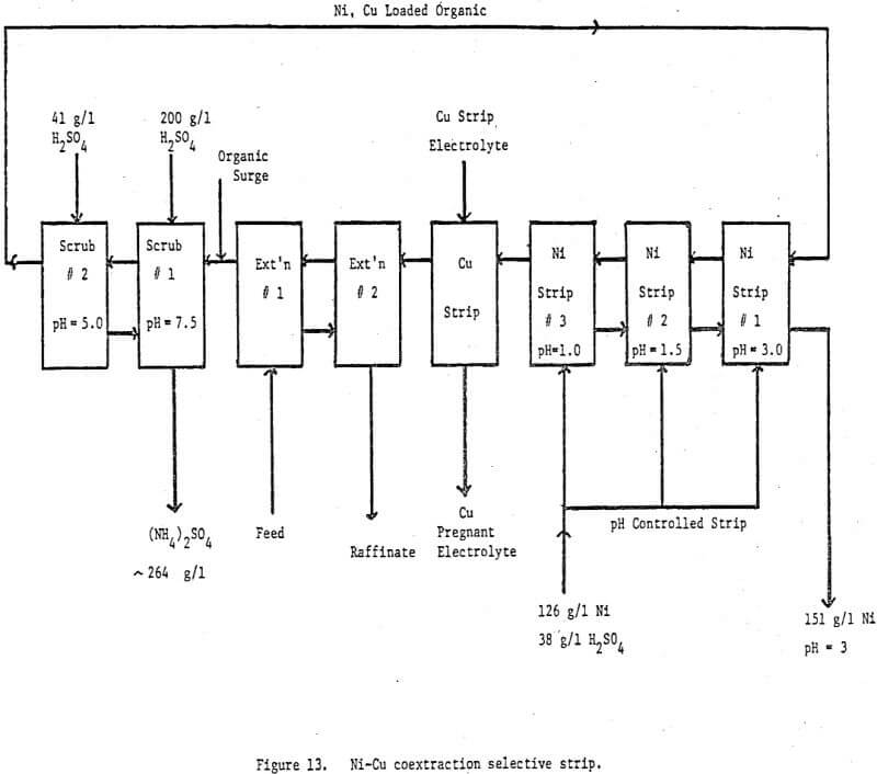
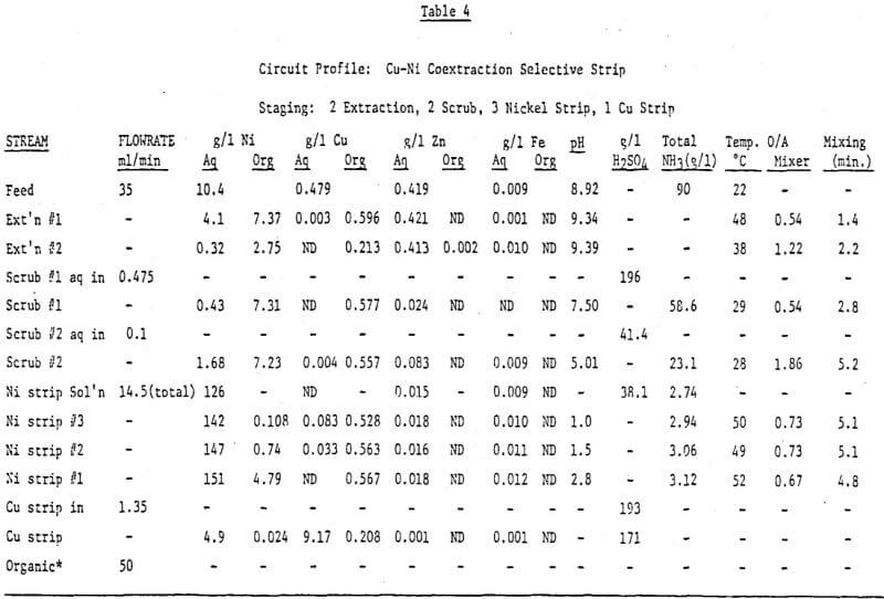
A second copper-nickel circuit was run on an ammoniacal leach solution generated by leaching a crude nickel sulfate obtained from a refinery bleed stream. The object was to further test our pH controlled selective strip and to try a new scrubbing technique. The feed contained —10 g/l Ni, —.5 g/l Cu, —.42 g/l Zn and 300 g/l (NH4)2SO4 at a pH of -9. The circuit diagram is shown in Figure 13 and a circuit profile in Table 4.
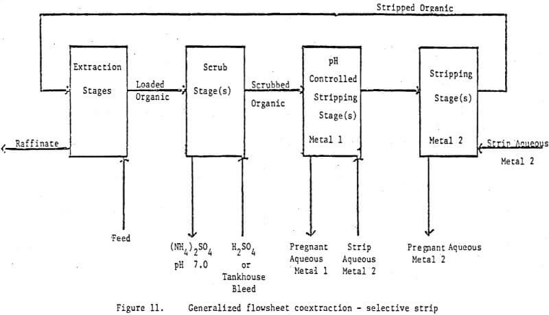
The major differences between this circuit and the one previously discussed is the addition of another scrub stage and the dropping of one strip stage for the selective stripping of nickel. The scrub section is designed to minimize any ammonium ion carryover to the stripping section. In the first scrub stage about 90% of the chemically bound and entrained ammonia is removed by pH controlling at 7.0 to 7.5 with 200 g/l H2SO4. The aqueous leaving this stage is 2 molar in ammonium sulfate but because of the neutral pH very little nickel is lost from the loaded organic and no nickel ammonium sulfate precipitates. The second scrub stage is pH controlled at 5.0 – 5.5 with 41 g/l H2SO4. This stage effectively removes most of the remaining chemically bound and entrained ammonia plus any zinc loaded on the reagent. Because the acid content is only -.4 molar the ammonium sulfate will only build to this level hence, any entrainment of this phase in the scrubbed organic will carry fewer ammonium ions to the nickel pregnant strip solution than if only one scrub stage were used. He recommend advancing the exiting scrub stream from scrub 2 to scrub stage 1. In this way the total nickel losses to the scrub system are only .06% of the total nickel transferred.
The three stages of pH controlled stripping also do their job quite well. The final nickel pregnant solution contains 151 g/l Ni, 3.12 g/l NH4+ and no detectable copper at a pH of 2.8. This solution is built from a nickel strip solution containing 126 g/l Ni, 2.74 g/l NH4+ and 38 g/l H2SO4. Total mixer retention time is 15 minutes at 50°C. From the nickel analysis of the organic exiting nickel strip stage 3 (.108 g/l Ni) it is apparent that a little more retention time in the nickel circuit would be helpful.
This circuit was not run with the intention of producing a nickel barren raffiante since the raffinate was recycled back to leach. Still 97% nickel extraction was realized and a slight increase in the reagent concentration would result in a better raffinate.
Conclusion
The technique of using direct, mixer pH control in solvent extraction circuits has been well demonstrated both in commercial circuits and in the laboratory. It is somewhat surprising that the technique has not been applied more widely in view of its successful application in the uranium industry. It is even more surprising when one realizes that there are examples in the literature and in our laboratory where pH controlled scrub stages were run to remove ammonia and small amounts of loaded zinc. In effect these scrub stages were functioning as pH controlled selective stripping stages but at the time were not recognized as such. Thus the technique was not extended beyond the scrub section.
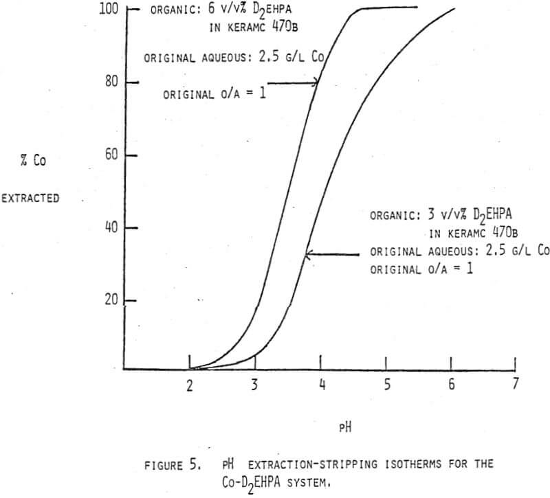
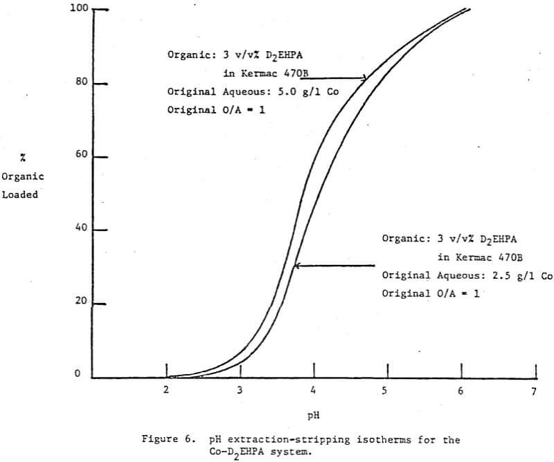
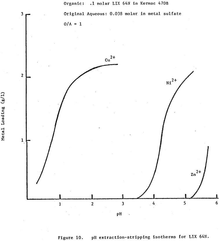
In theory any two metals may be separated by pH controlled stripping if their pH isotherms with a given extractant show some separation, provided the isotherms do not cross. The closer together the isotherms the greater the staging requirements and the more tightly the pH must be controlled. Even if the isotherms cross some partial separation should be possible. The exact staging requirements will vary as a function of the respective metal concentrations, the total extractant concentration and the stage efficiencies. The pH isotherms should be determined under conditions applicable to the system in question if the predictions for staging requirements are to be meaningful.
In simple terms the technique is nothing more than an automatic method to control pH over a very narrow range and thus it should be applicable to any system where pH control is needed or can be used advantageously. However, certain properties of some metal systems will limit the practical applicability of this technique. For example, nickel stripping suffers from slow kinetics and as a result long mixer retention times are needed. There may be some systems where the kinetics are so slow that retention times beyond reason would be required. A second example will be situations where a metal will have to be stripped in a pH range ideal for the formation of the solid metal hydroxide. This can lead to serious phase separation problems.
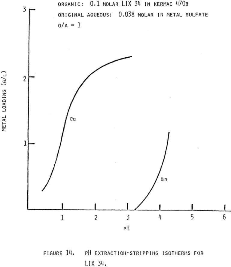
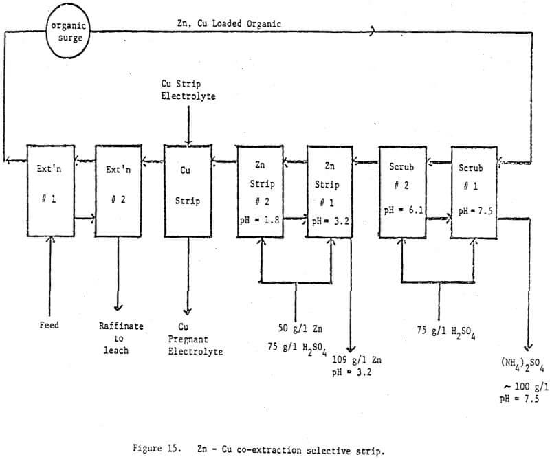
Future plans to test the concept of pH controlled circuits center on a three metal coextraction-selective strip system. A second experiment planned is the separation of two metals which have pH isotherms that lie very close to one another but do not cross.
