
Table of Contents
As part of its program to conserve the Nation’s natural resources by developing improved performance materials, the Bureau of Mines, U.S. Department of the Interior, in cooperation with the U.S. Department of Energy, has conducted an investigation of materials of construction able to withstand the high temperature and hostile environments encountered in coal gasification units. Refractory pipe liners are required when extremely hot gases or abrasive solids are transported between processing units in the gasification plants. One promising technique for producing refractory pipe (or refractory pipe liners) is centrifugal casting. For this study, the effect of processing variables such as workability, additives, reinforcement and spinning time, and centrifugal force were evaluated using four commercial refractory concretes. In addition, data on characteristics such as strength, density, abrasion, and spalling resistance of 5-inch-diam refractory pipe were developed. Techniques for forming large-diameter (19-inch) refractory pipe also were evaluated.
The test results indicated that all four refractory concretes could be made into strong, homogeneous pipe, but that optimum casting parameters had to be determined for each specific composition. The investigation revealed that the major controlling factor in the production of the centrifugally cast pipe was the workability of the refractory concrete.
Coal gasification processes require refractory linings in the gasifier unit, transfer lines between the preheaters and the gasifiers, and exhaust lines leading to the gas scrubbers. The major portion of piping used in coal gasification research development units is low-alloy grades of steel.
However, because of the erosive and chemically corrosive environments that occur in coal gasifiers, steel pipe can be expected to deteriorate after extended periods of service.
As part of its program to conserve resources by devising improved performance materials, the Bureau of Mines initiated in 1975 an investigation to develop a self-supporting ceramic pipe using centrifugal casting techniques. Subsequent to that year, the research was continued by the Bureau as part of an interagency agreement with the U.S. Department of Energy.
Research by the Bureau of Mines focused on the centrifugal casting process because slip casting techniques, which are generally used with finely divided materials, could not be effectively employed with coarse, nonplastic, refractory castables. The technique of centrifugal casting was first patented for manufacturing iron pipe in 1809. Since that time, reports have been published on casting of molten metal and basalt. Information also has been published on the techniques to cast concrete pipe. Although a novel technique called “sling casting” has been developed for casting a refractory material, there has been little or no work published on centrifugal casting of refractory concretes.
Review of the literature on centrifugal casting identified the following important variables:
- The raw materials must possess a controllable range of viscosity;
- the feed rate and method of introducing the feed to the centrifugal mold is critical;
- the rotational speed of the mold must be optimized and controlled to insure uniform distribution of feed within the mold and to density the formed piece; and
- a different rotational speed very often is used for mold loading and for densification.
Focusing on these four process variables, research was conducted at the Bureau’s Tuscaloosa (Ala.) Metallurgy Research Center to determine the effect of a number of variables such as water content, additives to increase workability, and spinning force and time on the centrifugal forming of pipe from refractory castable materials. This report presents the results of that work.
Centrifugal Casting Equipment
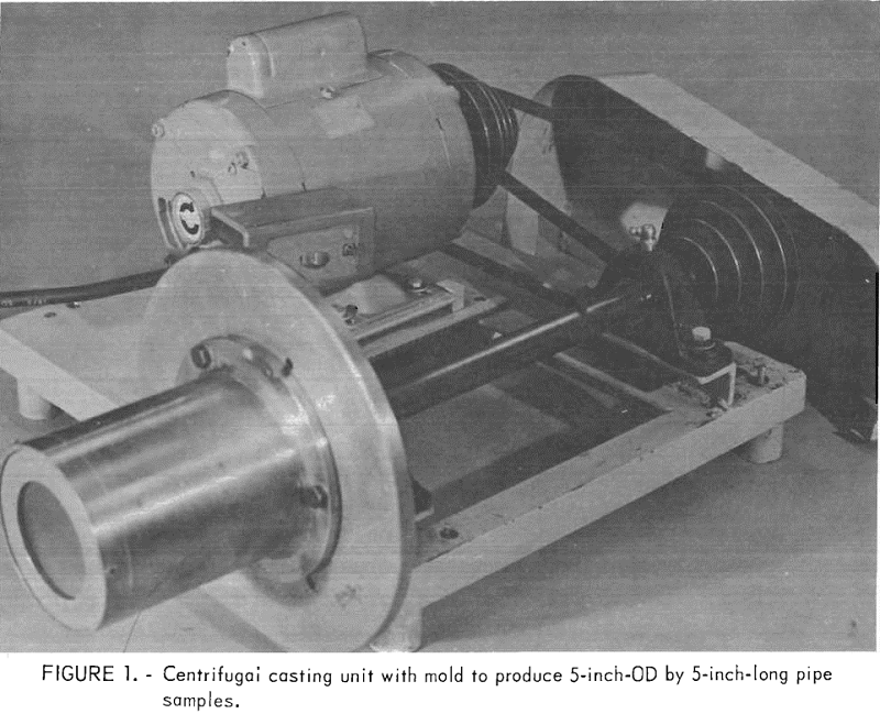
Several centrifugal casting units were used in the investigation. In one unit (fig. 1), the rotational speed of the stainless steel mold was controlled by a step pulley drive to yield peripheral speeds of 1,000, 1,500, 2,200, and 3,400 rev/min, creating densification forces of 57, 128, 275, and 657 G levels, respectively. Pipe 5 inches in outside diameter and 5 inches long and having a wall thickness of about one-fourth inch were cast in a balanced, tapered mold. After casting a pipe section, the mold with pipe was removed and a new mold bolted onto the drive mechanism to repeat the casting procedure. A waxed paper liner was used to allow easy removal of the pipe samples from the molds after curing and drying.
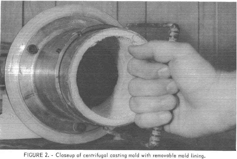
A modified unit was subsequently constructed utilizing a variable-speed motor that produced forces of up to 150 G levels. In this design, an untapered, removable, 5-inch-ID mold lining was inserted into an outer mold shell that was driven by the variable-speed motor. A view of the mold section is shown in figure 2. To facilitate mold release of the cast and cured pipe from the untapered liners, a wax coating that softened at the drying temperature (120° C) was applied prior to the casting operation. The pipe produced in this unit also was 5 inches in outside diameter and 5 inches long.
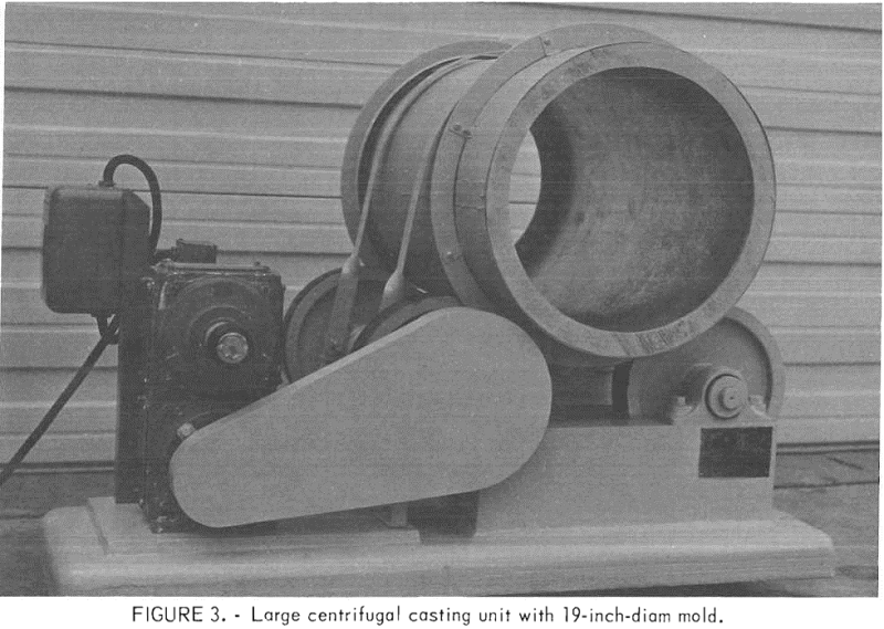
A large centrifugal casting unit also was constructed (fig. 3), in which the galvanized steel mold rested on four rollers, one pair of which was driven by a ½-hp, variable-speed motor. A pipe 36 inches long and 19 inches in outside diameter was cast using this unit.
A sling casting technique of fabricating pipe also was tested. The apparatus incorporated a vertical 22-inch-ID mold and a rotating, 12-inch-diam inner disk. The disk, equipped with vanes, was attached to the shaft of a variable-speed motor mounted on a platform of adjustable height. The refractory concrete was fed from the top of the unit onto the rotating disk. The vanes deflected the material, which, in turn, impinged upon the inner surface of the galvanized steel mold. As the material was deposited on the surface of the mold, the motor with rotating disk was lowered so that a relatively uniform thickness of castable could be applied along the length of the pipe mold.
Raw Materials
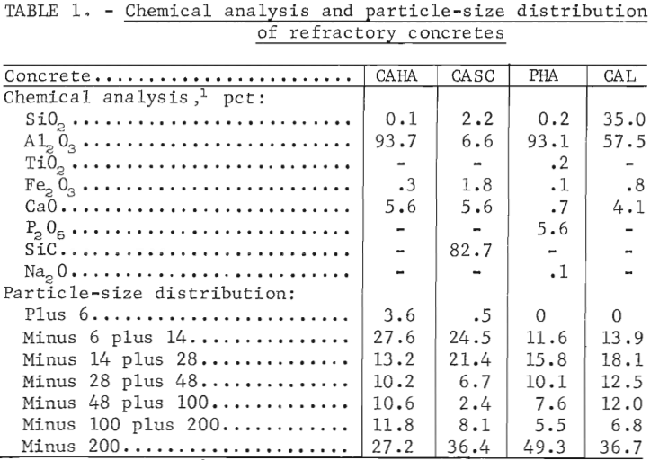
The four commercial refractory concretes used in the investigation were (1) a calcium aluminate-bonded, dense, high-alumina concrete (CAHA), (2) a calcium aluminate-bonded silicon carbide concrete (CASC) , (3) a phosphate- bonded alumina castable (PHA) , and (4) a calcium aluminate, light-weight, insulating castable (CAL). The composition and particle-size distribution of the four materials are given in table 1.
Two plasticizers were evaluated to determine the effect of the addition of plasticizers on workability of a castable and the strength of the formed pipe. The first was a 20-pct solution of polyvinyl alcohol (FVA) in water, and the second, a commercially available product, Hycol.
During the course of the research, stainless steel fibers approximately three-quarters inch in length with an effective radius of 0.013 inch were used to reinforce the cast pipe.
Preparation of Test Specimens
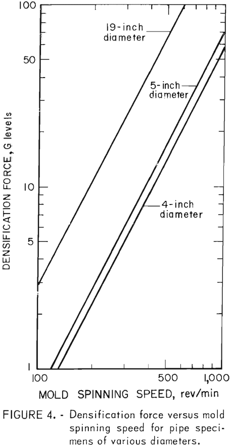
Samples of the calcium aluminate-bonded concrete products were dried at 120° C for 24 hours, packaged in moistureproof containers and allowed to cool to room temperature. In preparation for casting, samples of the dry material were mixed in a Hobart mixer for 30 seconds. A predetermined quantity of water was then added, and the slurry was mixed for an additional 30 seconds. The material below the mixer blades was turned with a spatula to insure complete blending, and the batch was mixed again for another 30 seconds. The slurry was charged into a slowly spinning (3 G levels) mold using a vibrating spatula. When charging was complete, the rotational speed was increased to produce a predetermined G level. The G levels associated with mold speed for specimens of 5- and 19-inch diameters are shown in figure 4. A final smoothing of the inside wall of the pipe was achieved by using a spatula. After casting, all calcium aluminate-bonded pipes were cured for 24 hours at 40° C in a cabinet maintained at 90 pct relative humidity, then dried for 24 hours at 120° C.
 Samples of the as-received PHA mix were kept in hermetically sealed containers until just before adding
water. The same mixing and charging procedure as described above was used. Pipe samples were heat-treated at 340° C for 6 hours as recommended by the manufacturer to permit the phosphate bond to develop.
When plasticizers were used to improve workability of the concretes, they were mixed in with the sample
prior to the addition of water. In the casting of pipes with fiber additions, the dry concrete mix and fibers
were blended before any water was added to minimize “balling” of the fibers.
For purposes of comparison, 2-inch cubes and 1- by 1- by 7-inch bars were made of each batch of material. Crushing strengths of the bars and cubes were determined and used as standards when comparing the crushing strengths of the various pipe compositions. The cubes and bars were cast in oiled metal molds that were vibrated to remove air bubbles.
Test Procedures
All crushing strength tests were made on the cast 5-inch-diameter pipes, bars, and cubes at room temperature. Before breaking, the thickness of the pipe wall was measured and pipe crushing strength for all 5-inch-long pipe was calculated according to equation 1.
γ = CS x (Di + t)/2 x 1/2t x constant……………………………(1)
where γ = crushing strength (lb/in²),
Di = internal pipe diameter (inch),
CS = crushing strength (lb/linear ft),
t = Pipe thickness (inch),
and Constant = 2.4, owing to a 5-inch (rather than 1-foot) length of pipe being tested.
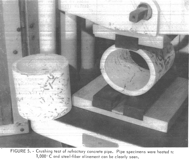
In determining crushing strengths, the pipes were placed between three rubber bearings and broken in a Tinius Olsen machine according to ASTM load-crushing test C497-75 for concrete pipe. The apparatus is shown in figure 5. The compressive strengths of the cubes were determined according to ASTM test C133-72.
The densities and erosion resistance of the cast pipes also were established. Densities of the pipes and cubes were determined according to ASTM test C20-74. The erosion test used was basically the same as that
described in ASTM test C704-72. Because the pipes were thinner than the ASTM standard test required, the test was modified somewhat. Less silicon carbide, only 500 grams as compared with the recommended 1000-gram charge, and a proportionately shorter abrasion time, only 4 minutes compared with the recommended 8 minutes, were used. All erosion tests were made on the inside surface of the pipe because this is the surface exposed to erosive particles and corrosive gases when in service.
A test to establish the spalling resistance of the pipe also was conducted. In the spalling test, pipes and cubes were heated for 10 minutes in a furnace at 1,000° C and then removed and held at room temperature for 10 minutes. The cycle was repeated, and after each quenching period, in ambient air, the test pieces were examined for cracks. If repeated cycling showed no visual deterioration of the samples, their crushing strengths then were determined to test for the presence of microcracks.
Where applicable, the Student’s t-test was used to determine whether there was a statistically significant difference (at the 95-pct level of confidence) in the average strength value measured for pipe prepared by different methods or produced from different materials.
Test Results
Preliminary Tests
Preliminary tests to establish the effect of water content, spinning time and speed, and the use of plasticizers on the centrifugal casting of pipe were made using commercial CAHA.
The Effect of Water and Plasticizer Additions
The quantity of water used in preparing CAHA must be carefully controlled. In this phase of the investigation, water additions of 10, 11, 12, and 14 pct were used. Additions of less than 10 pct or more than 14 pct water caused uneven wall thickness and aggregate segregation during the casting procedure. All pipe in these tests were formed at 1,000 rev/min (70 G levels) for 1 minute to give approximately 1/3-inch wall thicknesses. The results of these tests are given in table 2. Statistical analyses showed that there were no statistically significant differences in the strength of pipe made using 10-, 12-, and 14-pct water additions, and that optimum workability for this particular concrete was attained at 11- to 12-pct water content. The mix made with 10-pct water was only marginally workable.
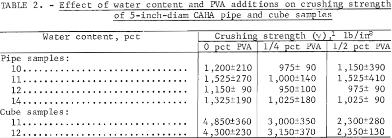
To determine possible adverse effects of plasticizers added to increase the workability of CAHA mix, crushing strength was measured for pipes and cubes made with additions of 0.25 and 0.5 wt-pct polyvinyl alcohol (PVA).
The additions improved the workability so that pipe could be easily formed from a mix containing as little as 10 pct water. Although the addition of PVA did not affect setting time of the castable, it did influence the strength of the pipes formed. As shown in table 2, strengths were significantly lower with PVA additions than without, except in the case of 0.5 pct PVA additions to pipe formed from 10- and 11-pct-water material.
Another series of tests was made using the commercial plasticizer, Hycol. Additions of Hycol of up to 0.2 pct increased the workability to such a degree that mix containing 11 pct water was too fluid to form pipe. The additive also accelerated the setting time of CAHA. Setting time was reduced to a point where it became difficult to even feed the material to the casting apparatus. As a result, work with Hycol additions was terminated.
The Effect of Spinning Time and Force
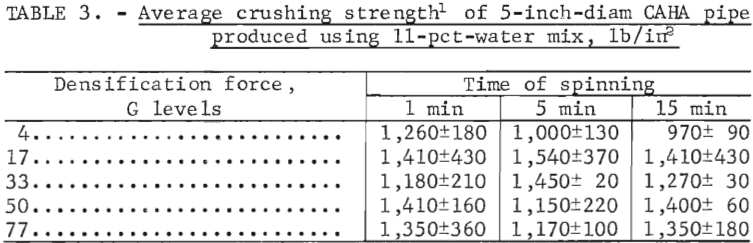
Pipe having a wall thickness of one-third inch from CAHA with an 11-pct water addition were evaluated at speeds that yielded forces of 4, 17, 33, 50, and 77 G levels for periods of 1, 5, and 15 minutes. No plasticizer was used in these tests. The results given in table 3 were statistically analyzed and it was found that neither spinning time nor G level significantly affected crushing strength. A spinning time of 1 minute was adequate. Optimum strength for the CAHA developed at about 17 G levels (500 rpm for a 5-inch- diam pipe).
Other Castable Compositions
Two additional dense refractory concrete compositions were evaluated. For these materials , the optimum water content for casting pipe was first established. With CASC, good-quality pipes were consistently produced at 13-pct water content. For PHA, only 7 pct water content was required to produce good-quality pipe.
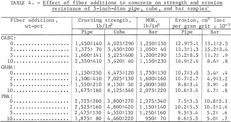
Using the established water additions, tests were made to compare breaking strength, density, and erosion resistance of cured materials. All pipes were cast at 4 G levels for 5 minutes,, Above 4 G levels, the PHA pipe displayed aggregate segregation. Strong, high-quality pipe of CAHA and CASC also were formed at this speed, but additional spinning at 75 G levels for 30 seconds was required to remove excess water that caused “slumping” of the concrete when the casting was completed. Three pipes having a wall thickness of one-half inch were cast of each material. For comparative purposes, modulus of rupture (MOR), density, and erosion determinations were made on 1- by 1- by 7-inch bars; crushing strength, density, and erosion measurements were taken on 2-inch cubes cast from the same mixes. The results of these tests are shown in table 4 (figures for zero wt-pct fiber additions). The PHA pipe proved to have higher strength values and higher erosion resistance than the other concrete pipes, but CAHA had significantly higher cube crushing strength and bar MOR. CAHA and CASC appeared to have relatively similar properties.
Fiber Reinforcement
To establish the effect of steel-fiber reinforcement on strength, pipes were made using 2-, 5-, and 10-wt-pct additions of a commercially available steel fiber to CAHA, CASC, and PHA. Pipes were formed from mixes using the water additions established previously. The pipes were cast using a force of 4 G levels and a spinning time of 5 minutes. To promote a more random arrangement of the ½-inch-long steel fiber, the wall thickness was increased from approximately one-third to one-half inch. Bars and cubes also were cast.
Visual observations indicated that the metal fibers were randomly alined in the pipe, bar, and cube samples. The results of tests to determine crushing strength and erosion resistance also are presented in table 4. The data indicate that the pipe crushing strength increased as the percentage of metal fibers increased for CAHA and CASC. Steel fiber additions significantly decreased the pipe crushing strength of the PHA formulation. The data also show that PHA pipe has higher crushing strengths than those of the other concretes at lower levels of steel fiber addition.
In the cube-crushing test, CAHA was stronger than CASC or PHA. Two-, 5-, and 10-pct steel-fiber additions significantly increased the strength of CASC and PHA cubes; CAHA was strengthened by additions of 2 and 5 pct but weakened by a 10-pct addition of the metal fibers. The MOR values on the bar shapes again show that CAHA was stronger than CASC or PHA. The MOR strength of CASC was not affected by fiber additions, but fiber additions of 5 to 10 pet increased the strength of CAHA. A 10-pct addition decreased the MOR strength of PHA.
The pipe erosion tests showed that PHA had superior erosion resistance at zero pct fiber addition than CAHA or CASC. Two- and 5-pct fiber additions decreased the erosion resistance of PHA pipe; 10 pct fiber addition decreased the erosion resistance of CASC. The erosion resistance of CAHA remained unaffected by the 2-, 5-, and 10-pct fiber additions. In the bar form, CAHA had a higher erosion resistance than any of the CASC formulations or PHA with 2-pct or lower fiber additions. Erosion resistance of CASC was improved by large (10-pct) fiber additions. A 5- to 10-pct fiber addition was required to show improved erosion resistance in PHA.
As can be seen from table 4, the mechanical properties of a concrete pipe cannot always be accurately predicted by the properties of cubes and bars made from the same material.
Spalling Resistance
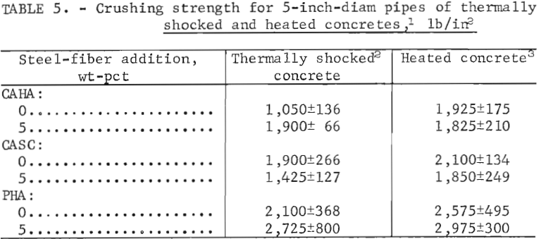
To determine the spalling resistance of the various refractory concrete pipe, samples were heated and cooled rapidly to induce thermal shock. Initially, the fiber-free CAHA and CASC pipe were treated to 34 thermal shock cycles. The samples showed no visual signs of deterioration. As a result, pipe samples without fiber additions, as well as pipe having a ½-inch wall thickness with 5 wt-pct steel-fiber additions, were prepared with CAHA, CASC, and PHA for the spalling-resistance tests. In these tests, the pipe samples were exposed to 10 thermal shock cycles before their crushing strength values were determined. It was assumed that microcracks produced by the thermal cycling would result in a decrease in crushing strength. The strengths of these thermally cycled pipe were compared with those of pipe that were slowly heated once to 1,000° C and slowly cooled. A view of a heated pipe showing the fiber distribution (made visible by color changes of the fiber-concrete- interface due to heating the pipe to 1,000° C) is given in figure 5.
The results of the tests (table 5) show that, when thermally cycled, all three concretes (with and without steel-fiber additions) showed a decrease in strength, with the possible exception of PHA with 5-pct fiber additions. The data also show that the CAHA and CASC pipe samples with fibers added had lower strength values than the samples without fiber addition after thermal shock treatment.
When the strength determinations were made on all pipe samples, it was visually apparent that the samples without fibers failed catastrophically, whereas pipe containing fibers did not. From these observations, it may be concluded that a pipe containing fibers may develop cracks through thermal cycling, yet resist catastrophic failure to a greater extent than unreinforced pipe.
Composite Pipe
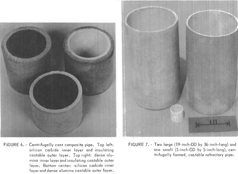
Several composite pipe also were successfully produced using the centrifugal casting technique, demonstrating that a total heat-containing unit (dense, erosion-resistant inner layer contained in an insulating outer shell) could feasibly be produced in the same mold. Figure 6 shows examples of three such pipe. The figure shows two pipe having an outer layer of CAL. One of the pipe has an inner layer of CASC (A); the other has an inner layer of CAHA (B). The third pipe in figure 6 has an outer layer of CAHA with an inner lining of CASC (C).
Large-Diameter Pipe
To determine whether any particular problems might occur in forming larger shapes, several 19-inch-diam by 36-inch-long pipe of CAHA were cast. A force of 20 G levels (270 rev/min) and a spinning time of 30 minutes were used to cast a 1-inch-thick pipe. The density of the cast pipe was 2.9 g/cm³, which approximated that of the smaller diameter pipe. A view of two large-diameter pipes is shown in figure 7.
Tests were also made using a slinger-type casting system, but satisfactory pipe was not produced because a section of pipe having a smooth and even wall thickness could not be made. When CAHA of very low water content was used, a large percentage of material was lost as a result of rebound. When a wetter mix was used, the material slumped from the mold surface.
Conclusions
Batch laboratory tests demonstrated that refractory concrete could be centrifugally cast to produce sound pipe. As a result of the research, the following conclusions were drawn:
- Processing parameters such as workability, spinning time and force, and charging methods must be determined experimentally for each concrete composition.
- Long spinning times and high G levels do not increase strength properties of pipe.
- Phosphate-bonded high-alumina concretes produce pipe of high strength and excellent resistance to erosion and spalling.
- The use of steel fibers improved the strength and spalling resistance of only the phosphate-bonded concrete pipe. In all the tests, however, the use of fibers prevented catastrophic failure of the pipe samples.
- Scaling up of the centrifugal forming process from the laboratory to produce large pipe from refractory concretes did not appear to present any difficulties , indicating that centrifugal casting equipment presently used in the concrete pipe industry can be utilized to produce refractory pipe on a commercial scale.
- The process is versatile in that fiber reinforcements can be added and composite pipe can be produced.