
Table of Contents
The objective for this U.S. Bureau of Mines (USBM) research is to evaluate construction and completion methods and costs for vertical in situ copper mining wells to depths of up to 1100 m (3600 ft). Appropriate construction materials and costs have been determined for well equipment, casing, drilling, cementing, and completion. A “deep” single ore-zone well design is presented for copper oxide or copper sulfide at a depth of about 1100 m (3600 ft). In addition, a multiple ore-zone well design is presented for a copper oxide ore body from 370 m (1200 ft) to 720 m (2360 ft). This design is to be considered generic even though the ore body setting is similar to that of the Santa Cruz In Situ Copper Mining Research Project near Casa Grande, AZ (Barter et al., 1993, Davidson et al., 1988).
According to Barter et al., (1993), the concept of in situ copper mining involves injecting a weak acid solution through a carefully constructed injection well into naturally occurring fractures in a copper deposit. As the solution moves through the fractures, it dissolves copper from the copper minerals it contacts. The copper-laden leach solution is collected in nearby recovery wells and pumped to the surface. At the surface, the copper is extracted from the solution in a solvent extraction-electrowinning (SX-EW) plant. The SX-EW plant removes the copper from the solution by plating the metal onto cathodes in electrically charged tanks. The remaining copper-depleted solution is reacidified, if necessary, and then recirculated through the copper deposit to extract more copper. Thus, the injection, recovery, and extraction is a closed-loop system.
The well designs presented should be considered as best estimates and were developed using engineering information from Barter et al., (1993), Davidson et al., (1988), and Errol L. Montgomery and Associates, Inc., (1992), and Pugliese et al., (1991). In addition, the catalog (World Oil, 1992) was used to identify companies that deal with pertinent well-system parameters. Specific companies were then contacted to obtain engineering information from knowledgeable persons of concern. A list of these persons and their companies are shown in the Acknowledgements section.
Costs were developed for the deep single ore-zone well design and the multiple ore-zone well design. Costs are shown for well equipment, casing, drilling, cementing, completion, and logging. The total cost of the injection well and the recovery well for each well design is also given. Costs were determined from Davidson et al., (1988), and from outside knowledgeable persons of concern mentioned above.
This paper has the following sections: (1) Introduction, (2) Order of Well Design Specifications, (3) Well Construction Materials and Equipment, (4) Well Completion Discussion, (5) Summary of Costs for Well Construction and Completion, (6) Conclusions and Recommendations, (7) Acknowledgements, and (8) References.
In this paper, dimensions are expressed in dual units. The equipment specifications were in inch-pound units, and then the metric dimensions were calculated from the inch-pound dimensions. In the case of hole and pipe calculated diameters, the values were rounded to reflect usual practice.
Order of Well Design Specification
The order of equipment specifications for designing an in situ mining well is important because later design factors are dependent on earlier design factors. For example, the downhole recovery pump diameter and flow rate will be factors in determining producer and injector well diameter which will affect the cost of the total well field. A boundary condition for this paper and analysis will be that all wells in the well field are identical and may be equipped to act as either producers or injectors.
The following represents the order of well design specifications used in this paper. This order and additional details may be found in Davidson et al. (1988).
In situ mining well design should be initiated by determining downhole equipment size requirements based on flow rate and depth values from manufacturer data tables. The recovery pump-motor diameter is the deciding factor of well diameter. Other equipment consists of: (1) tubing, (2) packer, (3) wellhead, and (4) fluid level instrumentation. Tubing provides a mechanical and hydraulic connection to downhole equipment. Packers are used to isolate fluids within one or more intervals of the well bore. The wellhead includes equipment that holds the downhole tubing string in place and provides pressure sealing and control of the tubing-casing annulus. During the in situ mining operation, fluid level in the casing-tubing annulus of the production well is monitored in order to maximize drawdown within pump limitations. In the injection well, changes in annulus fluid level indicates malfunction of the tubing, casing, or packer.
After determining downhole equipment sizes, the well casing strings, such as for intermediate casing and production casing within, may then be selected. An intermediate steel casing is used where unstable borehole conditions exist causing drilling difficulties. This casing provides additional protection for the production casing. The production casing acts as a conduit for well equipment and isolates injection and production well fluids from rock formations outside of the ore zone being leached. The production casing diameter is determined from the recovery pump-motor diameter and may be found in pump manufacturer data tables. Nominally, a cementing annulus allowance of 38 mm (1.5 in) may be used between the intermediate and production casing.
In addition to accommodating injection and production equipment, the casing and connections must withstand forces associated with casing installation, cementing, well stimulation, and fluid injection and recovery operations, and must also resist corrosion by process fluids. Casing design parameters depend primarily on well depth, equipment sizes, well fluid properties, and temperature.
In addition to the casing strings, other required casing equipment includes: (1) conductor casing, (2) centralizers, and (3) casing shoe, which is composed of a float valve, float shoe, pup joint, and a cementing plug. Conductor casing is used to prevent surface caving during well construction operations and must allow drilling equipment to pass through it. Centralizers are used to center the casing within the drill hole. In the casing shoe, the float valve is a one-way check valve located within and near the end of the casing string. The other one-way check valve, the float shoe, is attached to the bottom of the casing and has a rounded end to aid casing installation. These two valves are separated by a short casing (pup) joint. Pup joints are also used to obtain the correct casing string length. The float valve and float shoe are used to prevent displaced cement from flowing back into the bottom of the casing after cement pumping operations end. The cementing plug is pumped behind the cement slurry through the casing. The cement slurry is forced out of the casing into its desired location in the casing-hole annulus, and the cementing plug stops above the float valve.
The well drilling program is based primarily on casing size, well depth, cementing program, and geologic conditions. Hole diameter is determined basically by the casing outside diameter (OD), plus a cementing annulus allowance. This allowance could be 38 mm (1.5 in) between the production casing and hole. A 51-mm (2-in) allowance could be considered between the intermediate casing and hole. As a drilling equipment example, a 1220-m (4000-ft) class direct rotary rig is envisioned for drilling the 1100-m (3600-ft) holes. Selection of the drilling fluid is based in a large part upon its ability to minimize near well bore ore permeability damage. A polymer based mud system is recommended.
Well cementing provides a seal against fluid leaking between the well casing and the drilled hole and provides mechanical support for the casing. The cement grout must be compatible with prevailing geologic conditions, in situ leach solution, and casing materials.
Cement corrosion by sulfuric acid leach solution (typically used for in situ mining and heap leaching of copper oxide ores) occurs by dissolution of components of Portland-type cements, resulting in loss of strength and weight. Corrosion of the cement sheath around the well casing is generally confined to areas in the immediate vicinity of flow into or out of the formation, generally through perforations or slots which penetrate the casing, cement, and formation. Corrosion resistance of the cement may be enhanced by addition of small amounts of additives, such as bentonite.
Well completions refer to the means by which fluids are transmitted into and out of the well and may also be tied to well stimulation (matrix modification) techniques used to promote higher flow rates to or from the formation. Well completions may be open hole, screened or by casing perforation.
Open-hole completion involves only an open hole drilled through the ore zone. Screened completion is a variation of the open-hole completion in which a well screen is installed below the cased portion of the well.(Important screen criteria are covered in the well completion discussion of this paper.) Perforated completions involve opening an interval of cased well to the formation by means of creating multiple holes through the casing and cement sheath.
Matrix modification can be accomplished by explosive stimulation, high energy gas fracturing (HEGF), short-radius hydraulic fracture stimulation, and large radius hydraulic fracturing. Selection criteria for completion type and matrix modification method both are covered in Davidson et al. (1988).
Well logging may be used for geologic formation logging of the open drill hole. This logging will provide geologic information to be used in designing the well system. Other logging applications include measuring the cement bonding to the casing and formation, and making test and diagnostic measurements related to pressures and flow rates inside the well.
Regulatory requirements should be included in the order of well design specifications. Well integrity testing requirements will need to be ascertained. A permitting issue that may need to be addressed is the allowable volatile organic compounds (VOC’s) that may be generated by shaped-charge perforation. Details concerning VOC’s being products of combustion of downhole shaped explosive charges used for perforation are found in Errol L. Montgomery and Associates, Inc. (1992). Well clean-up procedures for VOC’s are also discussed in this reference.
Well Construction Materials and Equipment
In this section, the following will be discussed: (1) pump-motor specifications, (2) casing and tubing size and material, and (3) cementing. Some costs will be mentioned in the discussions. The well construction materials and equipment are to be considered generic, but information from the Santa Cruz In Situ Copper Mining Research Project will be used on occasion.
Electric Submersible Pump (ESP) and Motor: The ESP-motor system was chosen over other downhole pumps because it was considered the most suitable pumping system for the recovery of the copper-laden leach solution at the depths and flow rates considered for in situ copper mining wells (Davidson et al., 1988).
Centrilift and REDA are designing downhole pumping equipment that may operate in the acidic environment to be encountered by in situ copper mining methods.
Basically, the ESP-motor system is placed down the cased hole and consists of a motor on the bottom and a series of slotted impellers stacked above the motor, all in a housing. Each impeller is considered a stage of the pump. The impellers rotate which provide the lifting action of fluids within the casing. The ESP-motor assembly should be above the perforated zone but below the ground water level for improved cooling of the motor skin by the fluid passing by it.
As an example of the use of ESP-motor systems in deep, hot, and gassy wells in the Yowlumne oil field near Bakersfield, CA, ARCO and Centrilift reported that four ESP-motor systems have been successfully installed to depths up to 3600 m (11 800 ft) (Dittman et al., 1992). The first pump ran for 516 days while producing more than one million bbl of oil. Well conditions include bottom hole temperatures of 126.7° C (260° F). Also, H2S, CO2, and scale are present in most wells.
Cost and engineering information has been obtained for ESP’s and motors. In a personal communication, a REDA contact offered two preliminary pump-motor options considering the deep in situ copper mining application. The first is to lengthen an existing design to a 220-stage pump with a 18.6-kW (25-hp) motor. This pump-motor combination would be about 10.4 m (34 ft) in length, weigh 430.9 kg (950 lb), and pump 22.7 L/min (6 gal/min) to 45.4 L/min (12 gal/min) depending on the head being delivered. The pump diameter would be 86-mm (3.38-in) OD, and the motor diameter would be 95-mm (3.75-in) OD. This pump-motor combination would probably cost $70 000 to $80 000 each. To reach higher flow rates, a 147- stage pump and a 44.7-kW (60-hp) motor might be used. This pump-motor combination would deliver 95 L/min (25 gal/min) to 189 L/min (50 gal/min), be 9.8-m (32-ft) long, and weigh 453.6 kg (1000 lb). The pump diameter would be 102-mm (4-in) OD, and the motor diameter would be 116-mm (4.56-in) OD. This pump-motor combination would cost $80 000 to $90 000 each but would require $85 000 in development funding to bring it into production. The basic opinion of the REDA contact is that the 147-stage pump and 44.7-kW (60-hp) motor would be the better choice because of the larger motor and fewer stages in the pump.
Regarding the multiple ore-zone case, the REDA contact indicated that a 7.5-hp motor could be used with a 75-stage pump, and the system’s cost would be $25 000 to $30 000 each. The pump diameter would be 86-mm (3.38- in) OD, and the motor diameter would be 95-mm (3.75-in) OD.
In a communication with REDA personnel, the possibility of whether the above pump-motor combinations could fit into 140-mm (5.5-in) OD casing was discussed. At the time, being conservative with the 178-mm (7-in) OD casing was felt to be better although the possibility of using the 140-mm (5.5-in) OD casing should be explored. Driscoll (1986) recommends that the casing diameter be two pipe sizes larger than the nominal diameter of the pump and must be at least one nominal size larger than the pump bowl. The casing must be large enough to accommodate the ESP-motor with enough clearance for installation (and removal) and efficient operation. The diameter of the casing must also be such as to have adequate fluid flow and velocity within the casing to the pump.
The submersible motor generally does not withstand overheating and fluctuations in voltage (Driscoll, 1986). The motor is cooled by fluid passing over its housing and into the intake of the pump above. Overheating of the motor may occur if fluid in the casing cascades from above the motor. This problem can be overcome by placing a shroud over the intake of the pump. The open end of the shroud is below the motor. With pumping, the cascading fluid passes by the outside of the shroud and then is forced upward into the shroud. The fluid passes by the motor at the desirable velocity to provide the necessary cooling. The shroud may be made from oversizepipe, but the diameter of the casing needs to be large enough to accommodate the shroud. Concerning voltage fluctuation, the voltage should be maintained within plus or minus 10% of the motor name-plate voltage. Variation in voltage beyond this range may cause the motor to fail.
Casing and Tubing: As an example, FiberGlass Systems Inc. (“Star” Trade Name) provided a preliminary price for fiberglass high-pressure (13 790-kPa (2000- psi)) downhole casing with nominal OD’s of 140 mm (5.5 in), 178 mm (7 in), and 245 mm (9.63 in). The approximate cost respectively is $60.70/m ($18.50/ft), $90.22/m ($27.50/ft), and $147.64/m ($45.00/ft).
If the 178-mm (7-in) casing were to be used in deep wells ranging from 910 m (3000 ft) to 1100 m (3600 ft), the range of casing cost (excluding setting) for each hole calculates to be $82 000 to $99 000. If a thinner-walled 140-mm (5.5-in) casing could be used, the casing cost for each hole for the above depth range would be $55 000 to $67 000. Fiber Glass Systems Inc. also provided a comprehensive catalog of Star tubing, casing, line pipe, and fittings specifications (Fiber Glass Systems, Inc., 1993).
Cementing: Well casing is cemented into the drilled hole to provide mechanical support for the casing in both the vertical and radial directions and to prevent fluid flow in the annular space between the casing and hole (Davidson et al., 1988). Each well should be completed with a surface conductor casing, an intermediate casing string if unstable borehole conditions exist, and a production casing string. The cementing procedure in Barter et al. (1993), which pertains mainly to the Santa Cruz In Situ Copper Mining Research Project near Casa Grande, AZ, is suggested. Casings installed in the test wells were cemented over their entire length using specified cement mixtures. Cementing design considerations included: (1) assuring that the cement had sufficient density to offset buoyancy or other forces, and (2) assuring that the cement had adequate corrosion resistance so that the cement did not deteriorate over the life of the well. Table 1 contains details about the cement slurry mixes for surface conductor, intermediate, and production casings.
The blends in table 1 were determined after a preliminary evaluation by Metcom Research Inc., Tucson, AZ, of acid resistance of cement mixes. The test samples included ASTM Types II, V, 1P, and API Class G cements with bentonite ranging from 2% to 8% by weight. Acid solution strengths used in the testing were 20 to 80 g/L sulfuric acid and a 40:10:10 g/L solution of sulfuric acid, ferric iron, and chloride. From this preliminary evaluation, the following were concluded (Barter et al., 1993):
With increasing acid strengths, the ASTM Types II and 1P generally showed the best corrosion resistance at bentonite contents as low as 2%. One measure of corrosion resistance is attributed to the formation of a protective outer layer (calcium sulphate) that effectively seals the cement samples from acid attack. This protective outer layer translates into a weight gain for the sample. If a protective outer layer is not present, than another measure of corrosion resistance is a lower weight loss for the sample under acid attack.
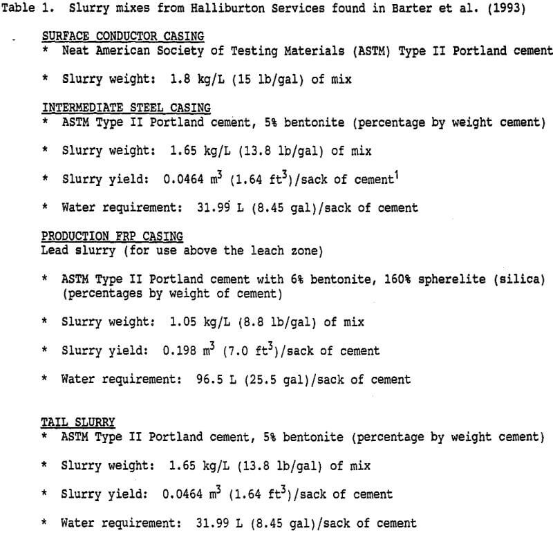
The addition of bentonite proved to be beneficial to all the cement samples tested. In general, a higher increase in sample weight during the test period was observed in samples with higher bentonite content. The thickness of the protective calcium sulphate layer was qualitatively observed to increase at higher bentonite concentrations.
The addition of spherelite to the Portland cement and bentonite mix resulted in a lightweight cement with optimal corrosion resistance, lower emplacement pressure, and decreased cement losses to the formation. Table 1 shows the percentages by weight of the lead slurry containing this additive for the production casing.
The most corrosive environment for all the samples tested was the acid-ferric-chloride leach solution mixed at a ratio of 40:10:10 g/L concentrations. The cements were tested with bentonite ranging from 0% to 8%. All of the samples tested were reduced in weight indicating that a protective layer was not formed in this environment. The ASTM Type II cement showed the lowest weight loss in this environment at all bentonite weight percentages.
Well Completion Discussion
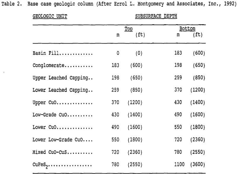
This section deals with: (1) open-hole and screened completions, (2) perforated well completion for a single ore zone, and (3) multiple perforated well completions. The discussions are applicable to in situ copper mining wells in general. However, on occasion, information will be used from the Santa Cruz Research Project. Concerning items (2) and (3), table 2 shows the general geologic stratigraphic sequence for the Santa Cruz test site (Errol L. Montgomery and Associates, Inc., 1992). In this reference, estimates are shown for permeability and porosity for each of the geologic units. This table will be used in the discussions of items (2) and (3).
Open-Hole or Screened Completion: According to Davidson et al. (1988), open- hole completion involves an open hole drilled through the ore zone below the well casing bottom. A screened completion is a variation of open-hole completion in which a well screen is installed below the cased portion of the well. The screen serves to prevent the open-hole portion of the well from filling up with debris from the formation. The value of a screen depends on how effectively it contributes to the success of a well (Driscoll, 1986). Important screen criteria are: (1) acceptable percentage of open area, (2) non-clogging openings (3) resistance to corrosion, and (4) sufficient column and collapse strength. Important screen characteristics include: (1) ease of development, (2) minimal incrusting tendency, and (3) low head loss through the screen.
Filter packing may be desirable if the zone immediately around the well screen needs to be made more permeable, or a drill rig with too large a minimum-hole-diameter limit is needed (Driscoll, 1986). For increased permeability near the well screen, some formation material would need to be removed by drilling a larger diameter hole and replacing this material with a specially graded sand or gravel that is smooth, uniform, clean, well-rounded, and siliceous.
Discussions with REDA personnel included the possibility of using open-hole or screened completions for deep well and competent rock application. The ESP-motor system would placed above the open-hole (screened) region.
The screened completion should provide better well control than the open-hole completion. According to Davidson et al. (1988), open-hole completion is seldom used for in situ mining unless the ore is in very competent rock, is unlikely to cave, or is unlikely to produce fines during operation. Details about different types of well screens and their installation as well, as filter packing, are contained in Driscoll (1986).
The following discussion on perforated well completion for a single ore zone applies to open-hole and screened completions with the exception that a production casing is used in the ore zone rather than an open hole or well screen.
Perforated Well Completion for the Single Ore Zone: The example reported here deals with an ore zone near 1100 m (3600 ft). Recovery and injection wells are assumed to be interchangeable. Directional fluid flow related to permeability in the ore zone should be addressed first to determine which wells would be started as an injection wells and which would be started as recovery wells.
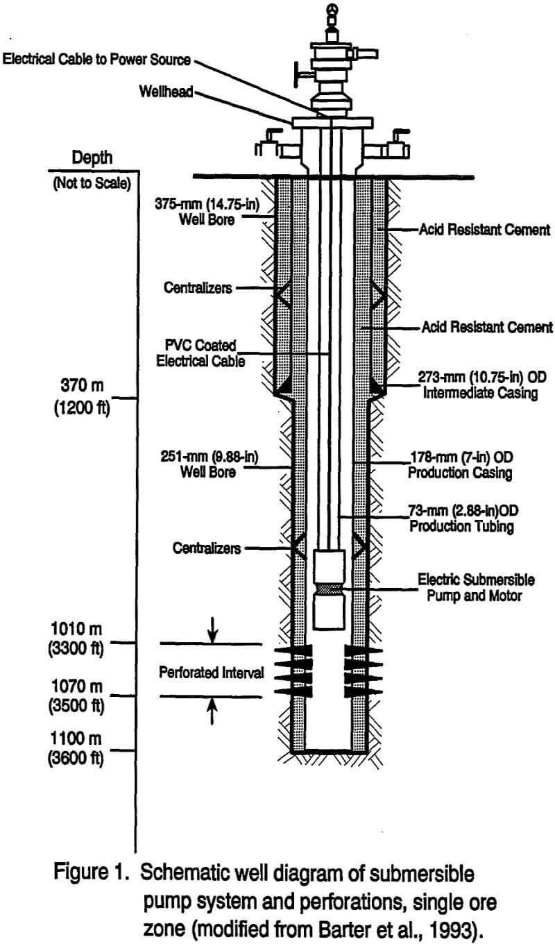
RECOVERY WELL: Figure 1 is a schematic diagram showing the location of the intermediate and production casing, the tubing, the ESP-motor assembly, and perforations for a 1100 m (3600 ft) in situ mining well (Barter et al., 1993). The conductor casing and casing shoe are not shown in the figure.
Referring to table 2 and figure 1, after installation of the 406-mm (16-in) OD diameter conductor casing in a 483-mm (19-in) hole to a depth of 6.1 m (20 ft), a 375-mm (14.75-in) diameter well bore would be drilled to 370 m (1200 ft), the bottom of the lower leached capping. Blank steel 273-mm (10.75-in) OD intermediate casing would be installed from land surface to a depth of 370 m (1200 ft). This casing would be positioned in the center of the well bore by centralizers spaced at 24.4-m (80—ft) intervals. The well annulus would be pressure grouted with acid-resistant cement from the base of the casing to the land surface.
Next, a 251-mm (9.88-in) well bore would bedrilled from 370 m (1200 ft) to 1100 m (3600 ft), and a fiberglass reinforced plastic (FRP) 178-mm (7-in) OD production casing would be installed from land surface to near total depth. This production casing diameter was a choice based on the recommendation that the casing diameter be two pipe sizes larger than the nominal diameter of the pump (Driscoll, 1986). Centralizers would be placed on the casing at approximately 18.3-m (60-ft) intervals. The well annulus would be pressure grouted with acid-resistant cement from the base of the casing to land surface. The hole would be sealed at the bottom.
The mechanical integrity of the casing would be tested to assure that the casing is well set and doesn’t leak. Generally, the test involves filling the production casing with water, pressurizing the water by applying a wellhead pressure, isolating the well from the pressure source (shutting-in), and measuring the wellhead pressure for a period of time (Barter et al., 1993).
After casing integrity testing, a 60-m (200-ft) interval in the ore zone would be perforated with a high efficiency gun system using 4 shots/0.305 m (1 ft) to allow injection and recovery of fluids. After perforation, a downhole video survey could be made to check casing integrity and verify perforation openings and intervals. The production casing above the perforated interval then could be tested for integrity by the procedure mentioned above. Here, a packer would be placed above the perforated interval before the testing.
Next, an ESP and motor would be set in the well preferably above the perforations by way of the tubing string. The tubing string to be used is FRP 73-mm (2.88-in) OD tubing and is connected to the top of the pump and leads to land surface. Electric power for the pump is conducted to the electric motor on the pump through a polyvinyl chloride (PVC) coated electric cable strapped to the outside of the tubing.
Once the ESP and motor are installed in the well, a representative sample of ground water may be obtained from the ore zone for a baseline chemical analysis. A chemical analysis of the water may indicate that VOC’s are in concentrations that exceed the Maximum
Contaminant Level (MCL) for drinking water. Concerning this, discussions were held with personnel at Schlumberger Perforating Center, Sandy Point, TX, and the Schlumberger Field Office at Lansing, MI. Those at the Perforating Center noted that VOC’s may be generated in the order of ppm’s from the shaped-charge perforating process. A bullet gun was suggested for use in perforating to circumvent creation of VOC’s. The bullet gun uses black powder which possibly could reduce VOC’s.
Clean up of the water containing VOC’s may be accomplished by using the procedures outlined in Errol L. Montgomery and Associates, Inc. (1992). These procedures include bailing particulate material from the well, removing the water from the well by pumping, swabbing and flushing the wells with ground water, containing the water produced by pumping, sparging the contained water until MCL’s for drinking water are achieved, and using the sparged water for dust control.
When shaped-charge perforation is being conducted and when cleaning out the crushed rock and charge debris from the well, pressure underbalancing by reducing pressure within the casing will allow fluid flow back into the well because of the higher formation-fluid pressure. Details on underbalance perforating used for clean up and higher well productivity are found in Dowell Schlumberger (1993).
Considering underbalancing at a depth of around 1100 m (3600 ft) and a water table depth of-around 152 m (500 ft), a pressure of 8274 kPa (1200 psi) is estimated from the formation fluid. The well bore would be at atmospheric pressure although having some fluid in the well bore may be desirable to curb against a violent flow-back action after perforation. Pressure underbalancing may aid in containing VOC’s. In addition to underbalancing and other completion techniques, details on modeling and gun systems are found in Dowell Schlumberger (1993).
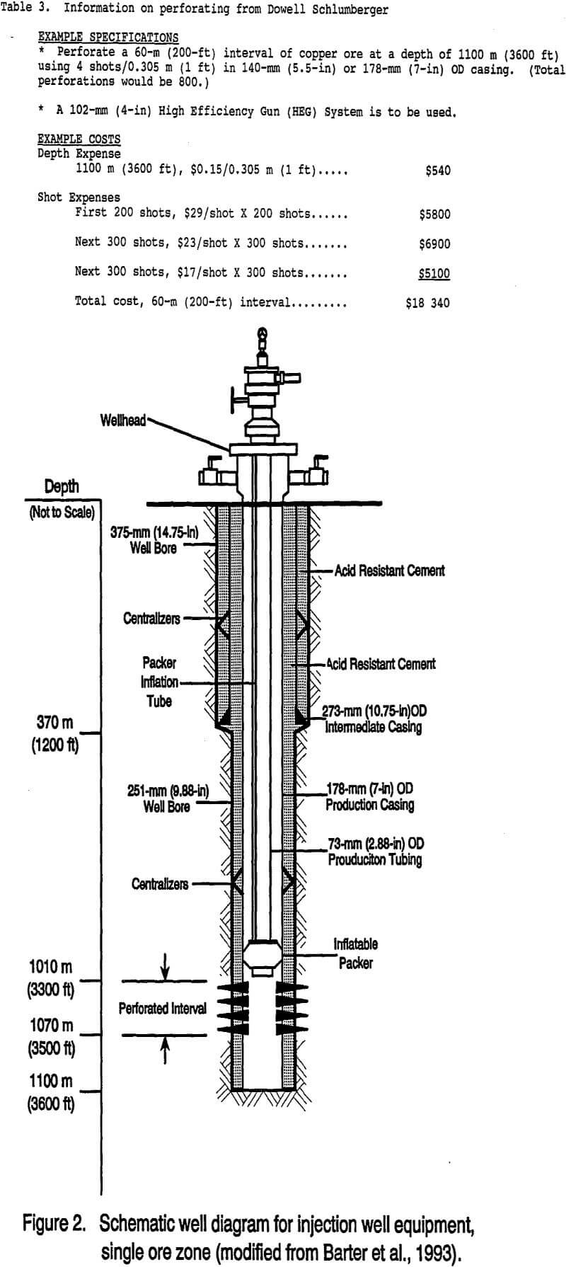
Table 3 shows an example from a Dowell Schlumberger representative whereby a 60- m(200-ft) interval of copper ore at a depth near 1100 m (3600 ft) is to be perforated by a High Efficiency Gun (HEG) System (102-mm (4- in) Gun, 90′ phased) using 4 shots/0.305 m (1 ft) in 140-mm (5.5-in) or 178-mm (7-in) OD casing. This gun system uses a secondary high explosive charge such as RDX.
INJECTION WELL
Figure 2 is a general schematic diagram for an in situ mining injection well and well equipment (modified from Barter et al., 1993). The injection well construction is identical to that of the recovery well. As stated above, the 178-mm (7-in) OD FRP production casing is set in cement to the bottom of the hole. The casing is perforated at the ore zone after the casing is well set.
The leach solution is injected into the ore zone after an inflatable packer is set above the ore zone. The packer is used in the injection well to isolate the high pressure leach solution within the desired injection interval and to avoid exposing the remaining well casing to leaching fluids and injection pressures. This practice provides additional protection of the well casing from damage (Davidson et al., 1988).
Multiple Perforated Well Completions: The example reported here deals with two ore zones with a significant separation between them. The generic ore zone setting used in this paper is similar to that of the Santa Cruz In Situ Copper Mining Research Project near Casa Grande, AZ. The average total depth of the CuO ore body is 720 m (2360 ft) (table 2). The Upper CuO and the Lower CuO ore zones were chosen for perforation. The Upper CuO ore zone occurs between 370 m (1200 ft) and 430 m (1400 ft). The Lower CuO ore zone occurs between 490 m (1600 ft) and 550 m (1800 ft).
For this example, injection and recovery were assumed to begin in the lower perforated ore zone which had the higher permeability (Errol L. Montgomery and Associates, Inc., 1992) and higher ore grade (Barter et al., 1993). The hole depth would be around 580 m (1900 ft). The upper perforated ore zone would be leached after recovery was completed for the lower ore zone.
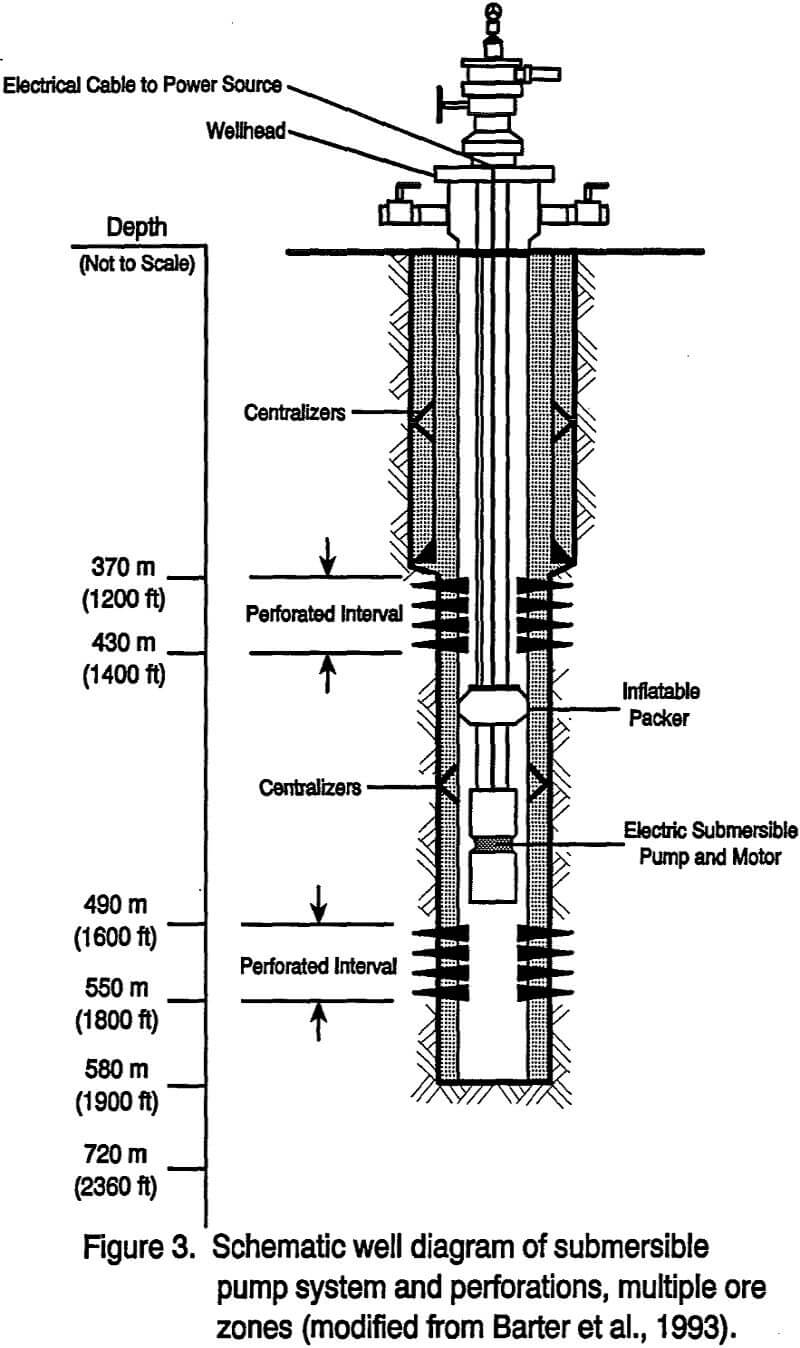
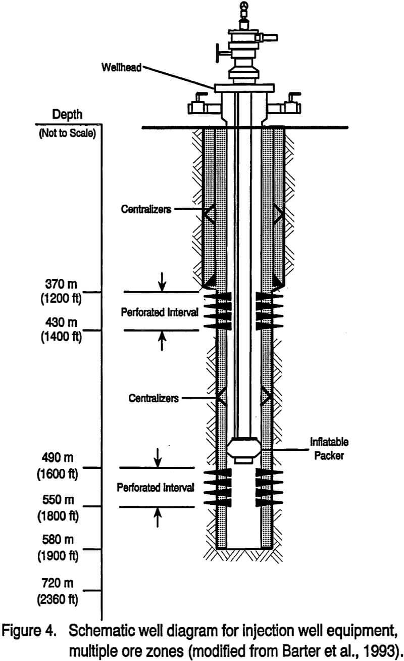
With the exception of depths, drilling and the casing string dimensions are found in the section on perforated well completion for the single ore zone and in figures 1 and 2. Figures 3 and 4 are schematic diagrams for recovery and injection wells to be used in multiple ore zones (modified from Barter et al., 1993).
RECOVERY WELL
Referring to figure 3 as a two ore-zone example, the casing strings are set in cement, sealed at the bottom, and tested for integrity. As one choice, the production casing then would be perforated at the two ore-zone locations which would require only one hole setup and trip through the well and would provide the best precision in locating all perforations. An alternative choice would be to perforate first only at the lower ore zone where recovery would then take place. The casing would then be perforated at the second higher ore zone location after recovery was completed at the first ore zone location. This choice would necessitate a second setup and trip through the well. For recovery, the ESP-motor assembly would be set in the production casing above the ore zone and pumping would begin. A well field priming time will be required for the leach solution to displace ground water in the ore zone.
When the casing at both ore zones has been perforated in one setup, the upper ore zone should be packed off when recovering from the lower ore zone. Sealing off this zone against ground water flow is important because the ground water would compete more favorably against the copper-laden leach solution in the recovery process. After recovery is completed from the lower ore zone, the ESP-motor assembly would be set above the higher ore zone. Recovery from this higher ore zone would begin after the lower ore zone is sealed off either by a packer or cement.
This upward stepping procedure may be used for cases where three or more ore zones exist. Two packers would be used to isolate an intermediate ore zone where recovery is taking place. One packer would be used above this intermediate ore zone if the lower ore zone(s)is cemented off.
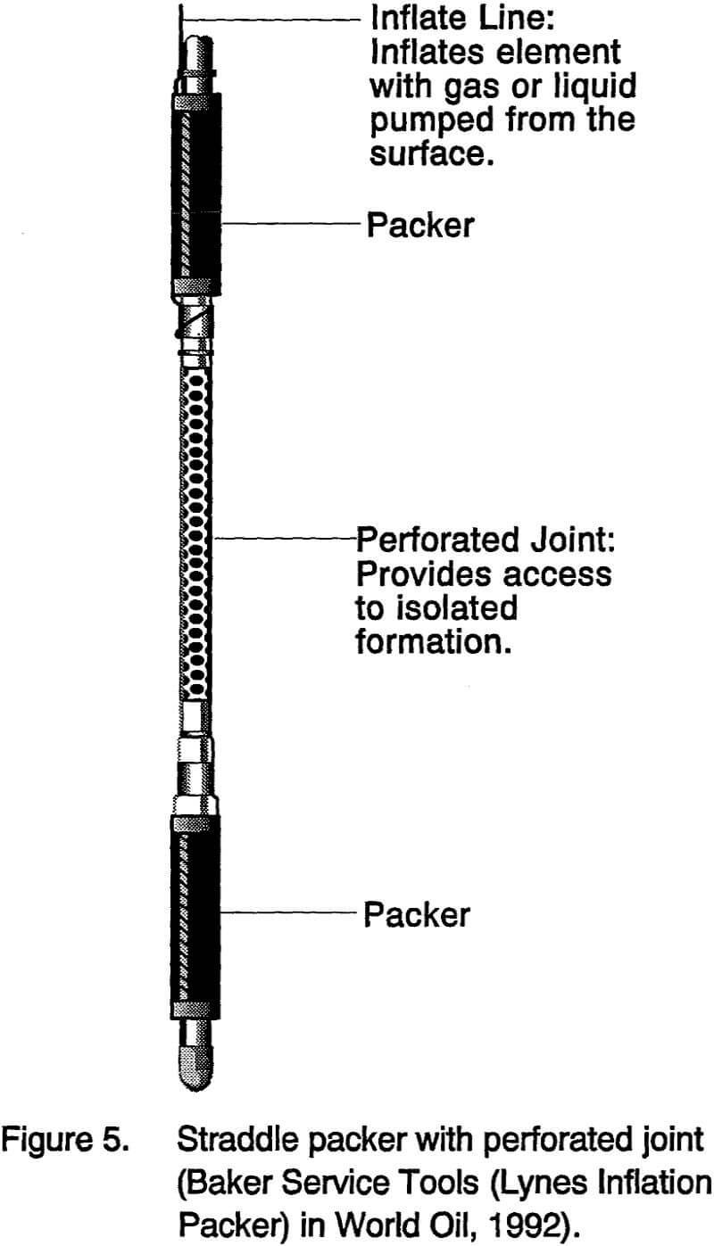
INJECTION WELL: Referring to figure 4 which is a two-ore-zone case, the casing strings are set in cement to the bottom of the hole. The production casing is perforated at the lower and upper ore zones or, as the alternate choice, at the lower ore zone. The leach solution is injected into the lower ore zone with an inflatable packer above this ore zone. The packer will aid in isolating the high pressure leach solution within the perforated interval and prevent exposing the rest of the well casing to the acidic leach solution and injection pressure.Moving up to the upper ore zone after perforation there, one choice would be to set packers below and above this ore zone to isolate it. Figure 5 shows a straddle packer assembly which could be used to isolate the injected ore zone. This figure shows the two inflatable packers with a perforated joint to provide access to the ore zone (Baker Service Tools (Lynes Inflation Packer) in World Oil, 1992). Then the leach solution is injected into this upper ore zone.
Another alternative for injecting into the upper ore zone would be to fill the production casing with cement at least to the top of the lower perforated ore zone before injecting. A packer would be used above the upper ore zone.
For injecting into three or more ore zones using packers, the lowermost ore zone would be isolated by the cemented hole bottom and one packer above. For each additional higher perforated ore zone, two packers would be stepped up the casing so as to isolate each additional ore zone. That is, each ore zone being injected would have a packer directly above and directly below. Or, the production casing would be filled to at least the top of the next lower ore zone before injection. Here, one packer would be used above the injected ore zone.
Summary of Costs for Well Construction and Completion
Costs are included for a perforated well completion in a single ore zone near a total well depth of 1100 m (3600 ft) and for multiple perforated well completions within a single well for two ore zones between depths of 370 m (1200 ft) and 550 m (1800 ft). For the following estimates, drill site development and drill placement costs, matrix modification costs, state sales tax, royalties, and sunk costs were not included. In addition, no extraordinary wages, difficulties, delays, or back-up equipment were assumed. The costs presented in tables 4 and 5 are to be considered nominal.
For the single ore zone case, the total costs of the injection and recovery wells were estimated to be $359 600 and $428 700 respectively. Table 4 summarizes costs for the deep injection and recovery wells and brief engineering details about well equipment, casing, drilling, cementing, completion, and logging.
For the multiple (two ore-zone) case, the total costs of the injection and recovery wells were estimated to be $274 700 and $293 600 respectively.
Table 5 covers the same particulars as table 4 but only for the multiple ore zone case.
For the two well completion scenarios, initial economic analyses were made to compare the cost of well construction and completion to the total cost of producing cathode copper. The cost model used was from Davidson et al., (1988) and Pugliese et al., (1991). In these analyses, a production rate (plant capacity) of 23 600 st/yr and a project life (construction time and plant life) of 18 yr were assumed. These and other cost and engineering input estimates for these analyses are similar to those in Davidson et al., (1988). In the analyses, adjustment was made for inflation. For the single ore-zone case, a calculated selling price of $0.70/lb for a discounted-cash-flow rate of return (DCFROR) of 20% was used. In this case, the well cost was estimated to be 30% of the cost to produce cathode copper. In the multiple-ore-zone case at a calculated selling price of $0.60/lb for a 20% DCFROR, the well cost was estimated to be 20% of the cost to produce cathode copper.
Conclusions and Recommendations
The order of well design specifications for designing an in situ mining well is important because later design factors are dependent upon earlier design factors. The order of the specifications given in this paper will allow the in situ mining well to be designed in a logical manner.
The recommended in situ mining well designs in this paper may be used as a starting point for designing, constructing, and completing injection and production wells in copper oxide and copper sulfide ore bodies, as well as other metallic ore bodies amenable to leaching by vertical wells drilled from the surface.
Future studies should include the following:
- Determine if screened (or open) completions can be used for vertical in situ copper mining wells.
- Explore further the possibility of using a bullet gun or water jet for perforation to circumvent the generation of VOC’s.
- Determine actual permitting requirements regarding well integrity testing and generation of VOC’s from shaped-charge perforation.
- In a partnership, explore the possibility of using horizontal wells for injection and/or recovery.