The following items make up an EXAMPLE Crushing Plant Startup Sequence & Procedure that all must be checked in preparation and before the equipment in the Crushing Plant is started.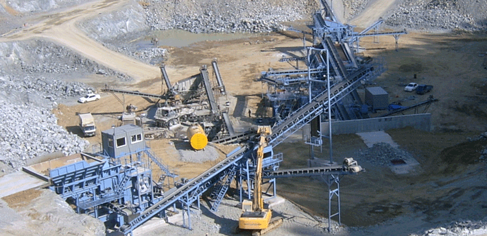
- If maintenance has occurred since the last operating shift, ensure that the MCC is energized and that all safety locks have been removed from equipment starters.
- Walk along all conveyors and check belt scrapers, idlers, and pulleys to ensure that there is no undue buildup of material or spillage. Check all conveyor emergency pull-cord switches; reset any engaged switches.
- Check all chutes to ensure that they are not plugged.
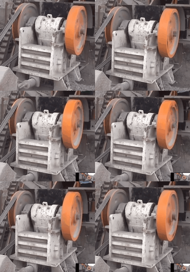
- Ensure that the cone crusher lube system is operational and that there is an adequate supply of oil in the reservoir.
- Remove and discard of any tramp metal dropped from the magnet onto conveyor #1 or #2.
- Inform the mill foreman or operator that the Crushing Plant is about to be started and that water from the dust scrubber bottoms pump will soon be pumped to the cyclone feed pump box.
Crushing Plant Startup Sequence
All the Crushing Plant equipment is interlocked, except for the sump pump, and therefore, the plant must be started from the fine ore bin back. The dust collector and scrubber bottoms pump are interlocked together, and must be started prior to other equipment. The sump pump should be placed in AUTO. The drives should be started in this order:
- Start the dust collector. Scrubber bottoms pump will start automatically.
- Place sump pump on AUTOMATIC
- Start either cone crusher lube pumps and allow 5 seconds for pressure to build up and oil to be circulated through the crusher.
- Start conveyor #3 (30 second horn will sound).* Start the cone crusher drive.
- Start the double deck screen. Once the screen has been started, a 15 second PLC timer will begin timing. Conveyor #2 and conveyor #1 must be started prior to the timer timing out (within 15 seconds), otherwise the conveyor #1 interlock to the screen will come into effect and stop the screen. If this occurs the screen should be started again to restart the sequence.
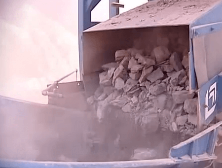
- Energize the electromagnet.
- Start conveyor #2 (30 second horn will sound).
- Start conveyor #1 (30 second horn will sound).
- Start the jaw crusher and allow it to come up to full speed before feeding it ore.
- Start the apron feeder and adjust the hand speed control to the desired feed rate.
- Safety codes require that a horn must sound for approximately 30 seconds prior to the start up of any conveyor. In this plant, when a conveyor start button is pushed, internal logic latches it in and a horn will begin to sound for 30 seconds, when the horn ends the
conveyor in question will start. In the startup sequence above, conveyor #3 will start as described; while the horn sounds, the cone crusher lube system can be started, and then the cone crusher. By the time the crusher is running, conveyor #3 will have started. When the start pushbutton for conveyor #2 is pushed, the internal logic will latch, sound the horn for 30 seconds, and start conveyor #2. As soon as conveyor #2’s start pushbutton is pressed, the interlock is made to allow conveyor #1 to start if desired. Pushing the start button for conveyor #1 during the horn sounding will extend the horn for a further 30 seconds. Therefore, starting conveyor #1 immediately after conveyor #2 limits the horn to a minimum.
Normal Crushing Plant Operation
 After the crushing plant has been brought up to normal operating conditions the operator should attempt to even out the feed to the jaw crusher to the design tonnage of 60 mtph. This is achieved by ensuring that the feed to the crusher maintains an essentially full chamber without ore spilling out. Adjust the speed of the apron feeder with to increase or decrease the feed rate to the jaw crusher and ultimately to the crushing circuit.
The product from both crushers should be visually checked to ensure that each crusher is producing the desired product. If the jaw crusher product increases in size, the cone crusher may become overloaded. Similarly, if the cone crusher product increases in size, the circulating load around the cone crusher will increase, consequently, increasing the load on the cone crusher and decreasing throughput.
The Crushing Plant operator must monitor the cone crusher power draw displayed on the cone crusher ammeter. The ammeter should show no major fluctuations and should read approximately 100 amps. An excessively high power draw on the cone crusher indicates the cone is being overloaded, which may be due to a high feed rate or a blinded screen.
The operator must pay close attention to the cone crusher lube system. A low pressure alarm will sound if there is an abnormally low oil pressure. If this alarm sounds, the crusher will shut down after a timed delay. If the crusher is allowed to operate longer than 2 minutes after the loss of oil pressure, serious damage to the crusher may result. If the pressure gauge indicates pressure above the normal operating pressure, shut down the cone crusher and investigate the problem. Likewise, a high temperature alarm will sound if there is an abnormally high oil temperature in the oil return line. 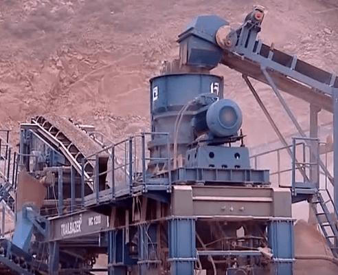
Shutdown the crusher and investigate if the temperature of the oil pipes seems excessive. Low oil pressure or high oil temperature may be caused by several conditions; insufficient oil supply in the lubrication system, a broken oil feed line, oil pump failure or excessive bearing wear in the crusher. Either condition must be thoroughly investigated as to the cause of the alarm.
Although there is no variable control of the belt conveyors in the Crushing Plant, the operator should regularly check conveyor discharge chutes to ensure there is no undue buildup of material. This is especially important if the feed material is “clay-like” or excessively wet.
The Crushing Plant operator must ensure that the dust scrubber has an adequate supply of reclaim water and monitor flow-meter to ensure that the proper amount of water is being recirculated through the scrubber. Under normal conditions, the dust scrubber requires a minimum recirculation of 8 to 10 cubic meters per hour. A lower flowrate will ultimately cause excessive wear on the scrubber and a higher flowrate is a waste of reclaim water and may hinder operation of the grinding circuit.
