


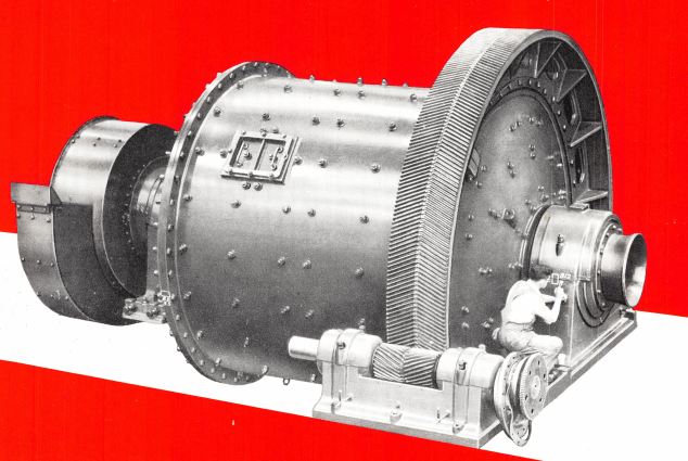
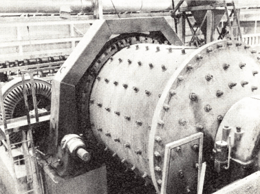
Common types of grinding mills include Ball Mills and Rod Mills. This includes all rotating mills with heavy grinding media loads. This article focuses on ball and rod mills excluding SAG and AG mills. Although their concepts are very similar, they are not discussed here.
Photographs of a glass ended laboratory ball mill show action of ball mass within the mill. The action of other grinding media is similar.
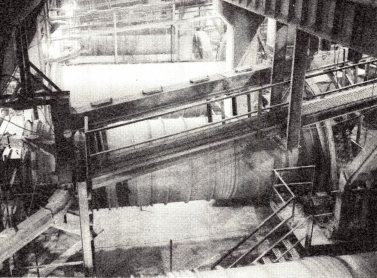
As the mill revolves, lifters assist in picking up the grinding charge and elevate it to an angle at which gravity overcomes friction and centrifugal force. The charge then cascades downward, effectively grinding particles of material within the mill by continuous, repeated impact and attrition action.
Grinding Mill speed is one of the factors affecting the character of the cascading charge. As shown in the illustrations, the lower the percentage of critical speed, the smoother the flow of balls from top of charge to bottom. Higher percentage of critical speed is used for impact grinding of large feed. Lower percentage of critical speed is used for attrition grinding when a fine product is desired. The graph below will be helpful in determining percentage of critical speed when internal mill diameter and RPM are known.
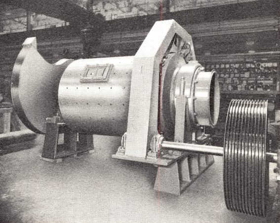
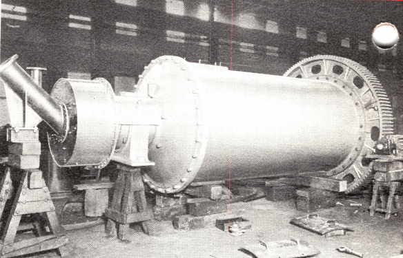
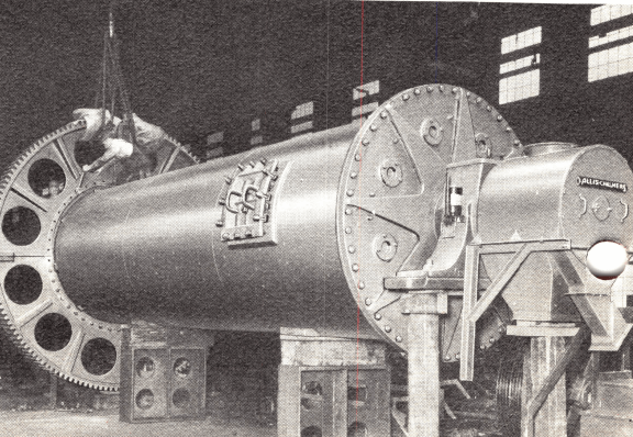
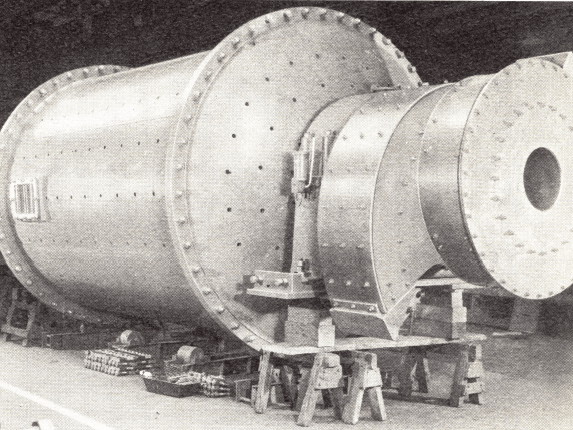
A Grinding Mill is a revolving cylinder loaded to approximately one-half its volume with steel rods, balls or pebbles.
Grinding mills reduce particle size by impact, rolling and sliding. Of the many types in use, the cylindrical mill, which employs a cascading mass of balls or rods, is universally used for the size reduction of hard, moderate to highly abrasive materials, such as minerals, ores, stone, and chemicals. ,
A cylindrical mill, when operating under uniform conditions, will produce a uniform product. Wear on grinding surfaces has little effect on capacity or product size. Very little maintenance is required with these mills, downtime being a negligible factor in their operation. For continuity of operation, the cylindrical mill has no equal.
Grinding mills of this type will give you dependable, trouble-free operation year after year, with “planned” periods of stoppage for renewal of parts. Initial cost is distributed over a long operating period. Many grinding mills are still in service after more than 40 years of almost continuous operation. Ton for ton of material handled, the cylindrical type mill has proved to be the most economical investment for reducing moderate to extremely abrasive materials.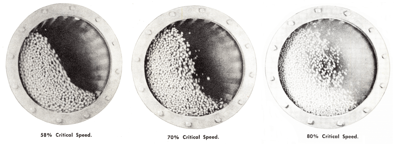
911Metallurgist sources manufacturers of all the proven mill designs in a “small” range of sizes — your assurance of getting the most suitable mill for your purpose. Best grinding efficiency and economy can be obtained only when the type and size of your mill is matched with your grinding job. Mills can also be furnished with modifications to suit any special application.
The choice between wet or dry grinding is dependent upon the use of the product or the subsequent process. It is imperative to dry grind many materials because of physical or chemical changes which occur if water or a solution are added. Wet grinding with water (or with a concentrated solution of the soluble salts being ground) is generally preferred, because of the overall economies of this operation.
Another factor in choosing a grinding mill is the consideration of the feed size introduced into the mill, and the product required from the mill or mill circuit. This can be best illustrated by comparing two prevailing and diametrically opposite grinds.
In the manufacture of standard cement by grinding cement clinker, the clinker is reduced from 1″ or finer down to a specific surface of 1750 sq cm per gram. This area can be produced by an open or closed circuit grind. The specific area method (which indicates the square centimeters of surface exposed per gram of material ground) is a most satisfactory method of determining whether a cement product will meet an accepted standard.
In a typical cement plant employing closed circuit grinding, 1750 surface can be obtained with a finish grind of between 93 and 96% passing 200 mesh. This area requirement means that fines are not only desirable but necessary, and that a size analysis must show a distribution of material from approximately 80 microns down to less than one micron.
When grinding ore prior to concentration, on the other hand, the grind is determined by the degree of reduction necessary to unlock the valuable mineral from the gangue. This gangue is undesirable and must be separated from the desired material. For example, the full-size illustration above shows a piece of coarse-grained magnetite. The grind necessary to unlock the magnetite is about 14 mesh. At this grind, almost every individual crystal of iron oxide is freed from associated gangue and the ground material is ready for magnetic concentration.
Actually then, the ideal grind would be to reduce this ore down to 14 mesh particles—not finer, for any expenditure of energy to reduce this ore beyond the unlocking mesh size is wasted. Such a grind is impossible, but any grinding circuit should be controlled so as to minimize overgrinding. Some fine material is produced, but it is tolerated rather than desired.
The same principles apply in grinding circuits for preparing feeds to flotation sections in the non-ferrous concentrators.
The product resulting from the reduction of a number of particles is dependent on two distinct shapes of grinding media—the rod and the ball. Here the term ”ball” is used to cover the entire range of grinding media which is spherical in shape, or roughly so.
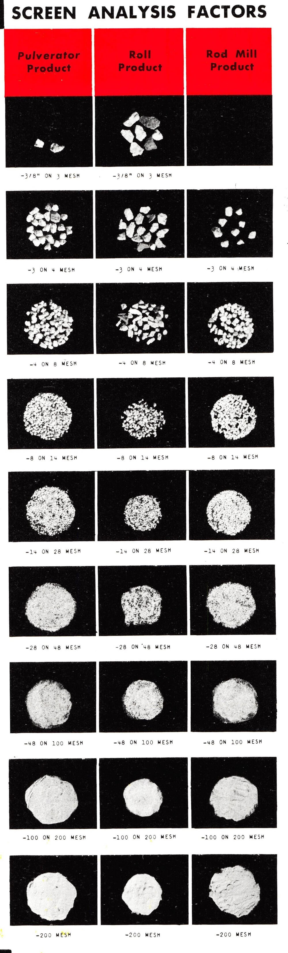
The principle of grinding action, rods as compared to balls, can be best understood by making a comparison of their contact with adjacent rods or balls. Rods making up a grinding charge are nearly parallel and tend to meet adjacent rods in line contact. Rods tend to bear only on the largest particles, thereby expending most of their crushing force on the over-size and allowing the fine particles a freer passage between the rods without being ground to objectionable fineness. Balls, on the other hand, meet adjacent balls in point contact and particles of material at these points are ground to a very fine state.
Generally, rod mills are used for:
Ball mills are used for:
Concavex grinding medium is an improved type of ball grinding media which offers more surface area per unit of weight, and has found extensive use in the grinding of cement clinker. The advantage of Concavex medium is its ability to increase mill capacity because of its interlocking shape and increased density per cubic foot of grinding charge. Surface areas for Concavex grinding media are given later.
Flint pebbles as a grinding media, are used where iron contamination is not permissible. Some operators use a screened fraction of their ore as grinding media.
 |
 |
 |
 |
These grinding mills are built in three basic designs:
Ball mills are built in Overflow and Diaphragm types. In the Overflow mill the material is discharged by new feed moving into the mill and displacing a mixture of solids and water being ground within the mill. The diaphragm arrangement in a ball mill is a positive means of pumping pulp or dry material out of the mill. The gradient is steeper than in an Overflow type mill. A Diaphragm ball mill has a higher capacity and requires more power than an Overflow ball mill of equal ball charge.
The Overflow rod mill is applied to wet grinding. The Center Peripheral Discharge rod mill is also used for wet grinding but produces a coarser product than the overflow type. Either the End or Center Peripheral discharge rod mill can be used for wet or dry grinding. Whatever the type, the rod mill is used to produce a coarse product, whereas the ball mill is used to produce a finer product.
Should a ball mill grind be required, the relationship of the length to the diameter of the mill is important. Feed and product screen analyses, and the type of circuit (open or closed), dictate the proper diameter to length ratio of a mill.
Characteristics of the short mill:
Characteristics of the long mill:
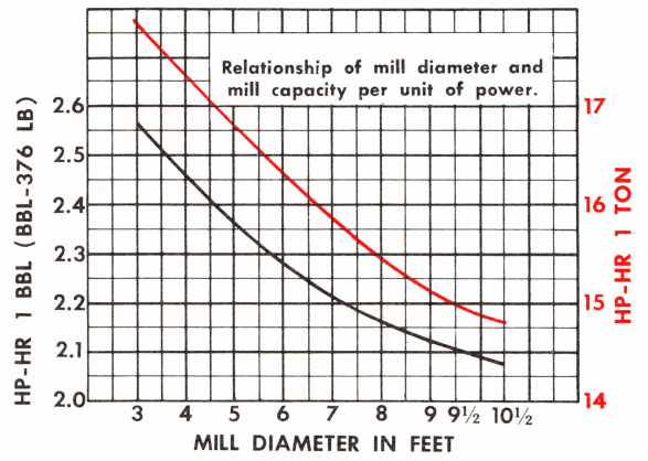
Regardless of mill length, the larger diameter mill provides a greater weight of balls per unit of mill weight and gives more capacity per unit of power.
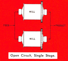 The type of mill for a particular grind and the circuit in which it is to be used must be considered simultaneously. Circuits are divided into two broad classifications, open and closed. In open circuit, the material is fed into the mill at a rate calculated to produce the correct finished product in one pass through the mill. This circuit has been popular in the cement and chemical industries, although the present trend is toward closed circuit installations. The closed circuit is generally employed in the mineral dressing industry.
In the closed circuit the material is discharged from the mill into a classifying device. The classifier separates and (1) returns the oversize material to the mill for further grinding, (2) delivers the fine material as finished product of that circuit. Material returning to the mill is called circulating load, and the ratio of this material to new feed may vary from a few percent to 600 percent or more.
Several types of separators are used in closed circuit grinding. Vibrating screens with screen cloth as fine as 28 mesh are used to produce a mesh product from either wet or dry grinding circuits. Fine wet grinding circuits employ a classifier to separate a product varying from 10 to 325 mesh. Fine dry grinding circuits employ an air separator for products of 65 mesh and finer.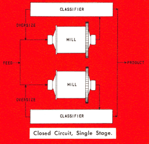
In open circuit grinding the feed rate must be low enough to permit a longer retention time per particle within the mill. This assures that each particle of the incoming feed, however large, will be broken down to product size. As a result, many particles in the product are ground to sub-sieve size. In ore dressing, these fine particles are usually undesirable, and the additional power required to produce them is a wasted expenditure. However, sub-sieve size particles are sometimes desirable, where the properties of the finished material require it. Finished cement and pottery glaze are examples of products requiring fines in the micron sizes.
In a closed circuit operation no effort is made to produce all the reduction during a single pass through the mill. Instead, every effort is made to remove a particle from the circuit as soon as it reaches the required product size. Quite often one of the largest particles of the feed, partially reduced, will be discharged, separated and returned to the mill several times before being completely reduced to the desired size.
When grinding to a specified mesh size, an increase in capacity is obtained by close circuiting the mill. This increase may be as high as 35 percent.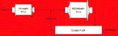
Open circuits are particularly useful where simplicity of the layout may be a determining factor . . . where a product containing ultra-fines is preferred … or where the material does not lend itself to handling in any classifying device.
All foregoing references to open and closed circuits apply to the ball mill. Because of the action of its grinding media, many rod mills are operated in open circuit, especially when preparing feed for ball mills. The rod mill, due to the character of its parallel grinding surfaces, simulates a slotted screen. The screening effect in the mill tends to retard the larger particles until reduced. Smaller particles slip through spaces between rods and are discharged without appreciable reduction.

Due to many variables, grinding is considered an art, not a science. A number of factors which affect grinding capacity are so variable that considerable engineering experience is required for a judicious selection of the proper mill and circuit for a given operation.
The following equations and tables express some of the better known empirical rules and can be used as a guide for mill selection.
Some operators prefer the high speed mill, others will consider only grinding mills operating at low speeds. Grinding mill speed, it should be noted, is not absolute, not a definite rpm, but relative to a quantity called critical speed.
The critical speed of a mill is defined as the lowest rpm necessary to centrifuge an infinitely small particle next to the shell lining within the mill. By equation: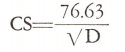
where CS=Critical speed in rpm.
D=Internal diameter of mill inside the shell lining, in feet.
The critical speed graph, Fig. 2, is a representation of this formula. Photographs illustrate ball behavior in mills operating at various percentages of critical speed.
Mills are operated at between 55 and 85 percent critical speeds. Generally, the smaller diameter mills operate at a higher percentage of critical speed than the larger mills.
The following statements can be made concerning the horsepower demanded by a mill, all other factors remaining constant:
Allis-Chalmers recognizes these, as well as other factors influencing HP requirements, and has developed an equation for calculating mill HP. This equation, as applied to dry grinding diaphragm ball mills, is as follows:
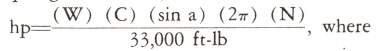
HP=HP per ft of mill length.
W=Weight of grinding charge and material per ft of mill length.
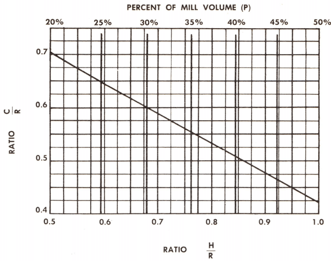
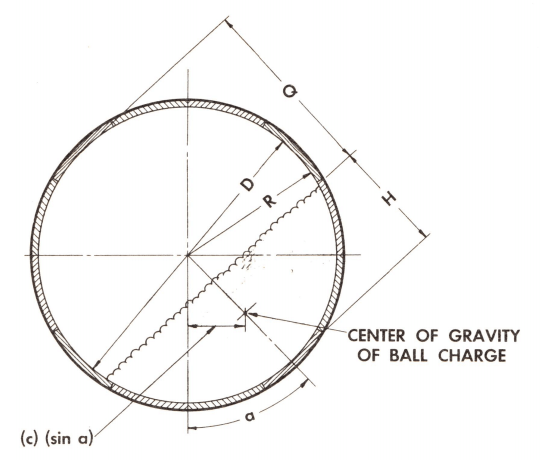
C=Distance in feet from center of mill to the center of gravity of the grinding media.
a=Dynamic angle of repose of grinding charges, usually 43° for dry grinding slow speed ball mill, 51° for normal ball mill speeds.
*The theoretical exponent is 2.5, but actual results indicate that 2.6 is more nearly correct.
Fig. 1—Table of 2.6 Power of Frequently Used Mill Diameters.
|
Internal diameter |
Diameter 2.6 | Internal diameter |
Diameter 2.6 |
| 1.25 | 1.8 | 5.5 | 84 |
| 1.5 | 2.9 | 5.75 | 94 |
| 1.75 | 4.3 | 6.0 | 105 |
| 2.0 | 6.1 | 6.25 | 117 |
| 2.25 | 8.3 | 6.5 | 130 |
| 2.5 | 10.8 | 6.75 | 143 |
| 2.75 | 14.9 | 7.0 | 157 |
| 3.0 | 17.5 | 7.5 | 189 |
| 3.25 | 21.5 | 8.0 | 221 |
| 3.5 | 26.0 | 8.5 | 260 |
| 3.75 | 31 | 9.0 | 302 |
| 4.0 | 37 | 9.5 | 348 |
| 4.25 | 43 | 10.0 | 400 |
| 4.5 | 50 | 10.5 | 452 |
| 4.75 | 58 | 11.0 | 510 |
| 5.0 | 66 | 11.5 | 575 |
| 5.25 | 74 | 12.0 | 640 |
N=Speed in RPM
D=Mill diameter, inside liners, in feet.
H=Height of charge, expressed in feet.
Q=Maximum vertical distance from top of charge to shell liner.
(H, D, Q are for later use.)
The quantity C is the most difficult to determine. The graph, Fig. 5, indicates how C may be calculated if the percent charge, or if the height of the charge H is known.
A 7 ft diameter dry grinding diaphragm mill has a 40 percent ball charge and a speed of 23.6 rpm. What is the horsepower per foot of length? The mill has 2 in. thick shell liners.
The dynamic angle of repose, a, is impossible to determine, and is calculated from the equation by substitution of all other factors. Once determined for a set of conditions, angle a can be substituted in the formula for any horsepower calculation. The horsepower so obtained is sufficient to cover fractional losses in the bearings and drive.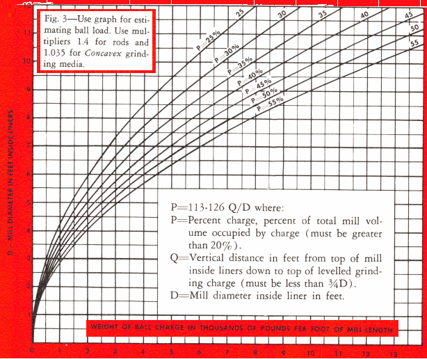
From quantity (W) of the equation, it is obvious that the mill horsepower is proportional to the apparent density of the grinding media. Also, mill horsepower is proportional to the angle of repose of the grinding media. That’s why Concavex grinding media increases a mill’s horsepower. Concavex media has a slightly greater apparent density. Because of its shape, it interlocks more than balls, resulting in a higher angle of repose.
The horsepower equation was developed to meet the conditions of a dry grinding diaphragm mill. Empirical conversions are:
Wet grinding diaphragm hp=0.90 dry grinding diaphragm hp.
Wet grinding overflow hp=0.85 wet grinding diaphragm hp.
The equation shown in the graph below will be helpful in determining the percent charge in specific mills, knowing Q (see Fig. 4). A definite charge percent and weight can be calculated for a desired value of Q, or the distance below the mill centerline (Q-D).
One of the oldest; and most reliable methods of determining the horsepower-hours required per unit of grinding capacity is to get comparable information from an existing operation which is grinding a similar material to the same grind.
Frequently however, when an operator is faced with selecting a mill of proper size, there is no existing operation he can turn to for comparison that parallels his proposed grinding conditions.
To select a mill size by this method, it is therefore essential to have laboratory grindability results on a large number of commercially ground materials and to have this grinding data in considerable detail.
We have tabulated results of grindability tests covering a wide variety of materials and product specifications of commercially ground materials. These test results are a reliable guide in relating the grinding characteristics of your material to a material that is being ground in an existing operation.
In brief, three factors are required to determine the HP-hr per unit of capacity of the unknown material:
These factors may be used in the formula: HPu/HPk = Gk/Gu
This equation should only be used if the grindabilities differ by less than ten percent.
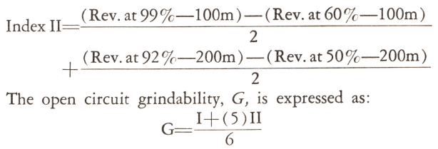
We employ two methods of determining a material’s resistance to grinding. One is made by grinding to a specific mesh size. The grindability index, G, is expressed as grams produced with a definite percentage of circulating load.
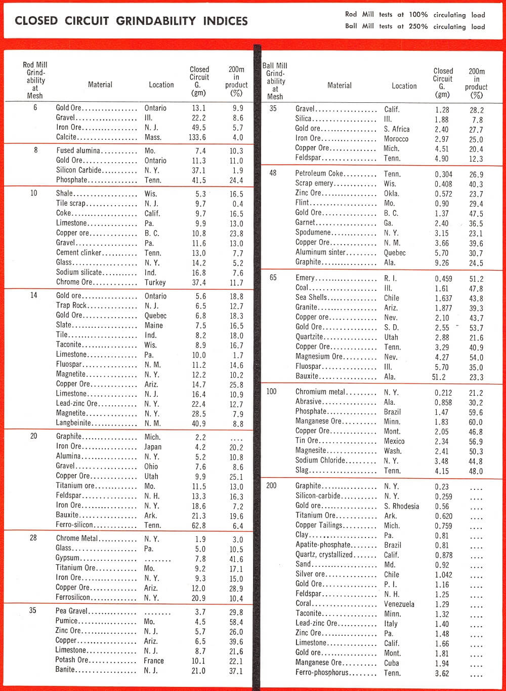
The other method is applicable to materials ground in the cement and chemical industries, where no specific mesh size may be required, but a definite surface area must be produced. Essentially, this test simulates an open circuit by grinding the sample in a ball mill until 85 percent passes 20 mesh. The ball mill product is further ground in a jar mill until 92 percent passes 200 mesh. Index I is derived from the product screen analvsis plot of the ball mill test: 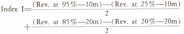
Index II is derived from the product screen analysis plot of the jar mill test:
The open circuit grindability index as determined above, and when used with accurate, detailed field data, serves as a method of determining the hp-hr required per unit of capacity.
Selected grindability values are tabulated here below. For a more complete selection of work indexes.
Occasionally a test is requested on a material for which field data does not exist. The grindability test is still useful, but it is recommended that a verifying pilot plant test be made when a large operation is planned.

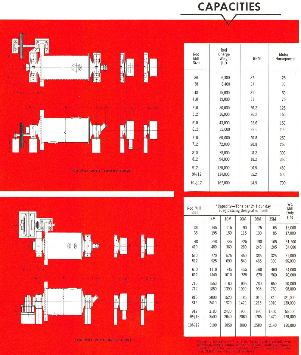
In recent years, rod mills have found increasing use in preparing ball mill feed. The rod mill is exceptionally well suited to handle coarse feed and to control the top size of the product. Rod mill products are generally coarser than those produced in a ball mill. Because of these characteristics, the rod mill has also found wide acceptance by manufacturers of fine concrete aggregates, where rigid state or federal specifications must be met.
Rod mills are also used extensively in the grinding of chemicals, coke, limestone, slag, etc. It has been a general practice to build rod mills in lengths of 10 to 12 feet. This permits the use of rods of sufficient length to perform screening action, retarding the passage of oversize particles through the mill until reduced to product size and finer.
Where a finely divided product must not be adulterated by iron, the pebble mill is the logical choice. These mills are lined with a non-metallic material such as porcelain or stone, and employ flint or stone grinding bodies. Thus, iron contamination caused by grinding is kept to a minimum. This is an important consideration in the glass sand, scouring powder, talc, and ceramic industries.
Since pebble grinding bodies have a density of about one-third that of metallic media, these mills are of lighter construction and require only about one-third the horsepower of a ball mill of equal size. Capacity is approximately one-third that of a ball mill.
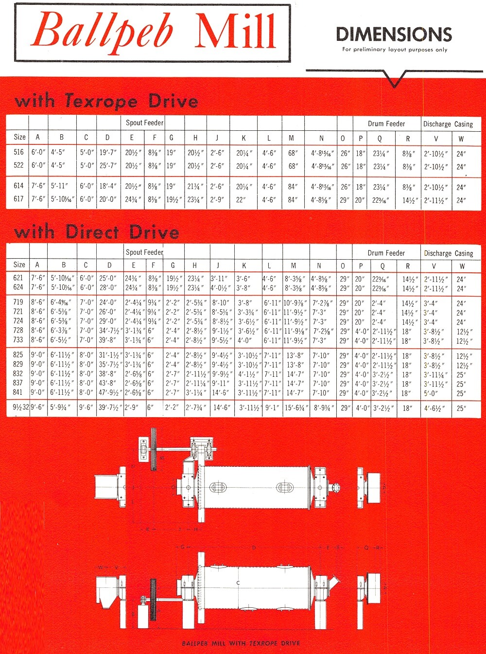
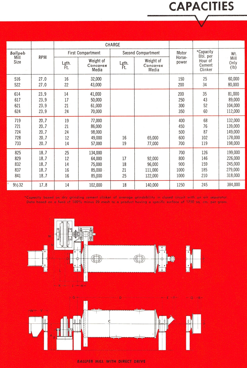
A Ballpeb mill is a secondary ball mill having either one or two compartments. This mill is specifically designed for operation in series with a Preliminator mill, or as a finish grinding mill with small size feed. Ballpeb mills will produce a finished product from relatively fine feed in open or closed circuit. The Ballpeb mill will take the product of a Preliminator mill and produce finished kiln feed, finished cement, mine dust, sized calcined coke, etc. These mills are equipped with thinner shell liners and employ smaller size grinding media than Preliminator mills.
Ball mills originally were used to grind approximately 2 in. material to pass 10 to 80 mesh screens. Present day practice is to use a feed of about 1/2 in. or finer. Product size has become increasingly finer and no actual grind limit is indicated.
The principal field for ball mill grinding has been the metalliferous ores and the more abrasive minerals. Because of the mill’s inherent characteristics of simple operation and low maintenance, it is gaining acceptance for grinding materials formerly ground in other types of mills.
Ball mills used in the mining industry are invariably short, the length being roughly equal to the diameter. When close circuited with a classifier, the short length of the mill and the high circulating load allows a short retention time with minimum overgrinding.
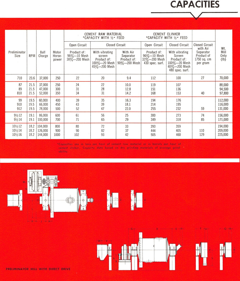
The Preliminator mill is a type of ball mill used for coarse grinding in open circuit or for fine grinding in closed circuit.
Preliminator mills are widely used in the cement industry for the reduction of cement raw materials and clinker. It is also used for the reduction of abrasives, refractories, limestone for mine dust, etc.
These mills can handle 1 in. feed. To grind this large feed efficiently, Preliminator mills are provided with thick shell liners and employ large balls as grinding media. Length is generally equal to or somewhat greater than the diameter.
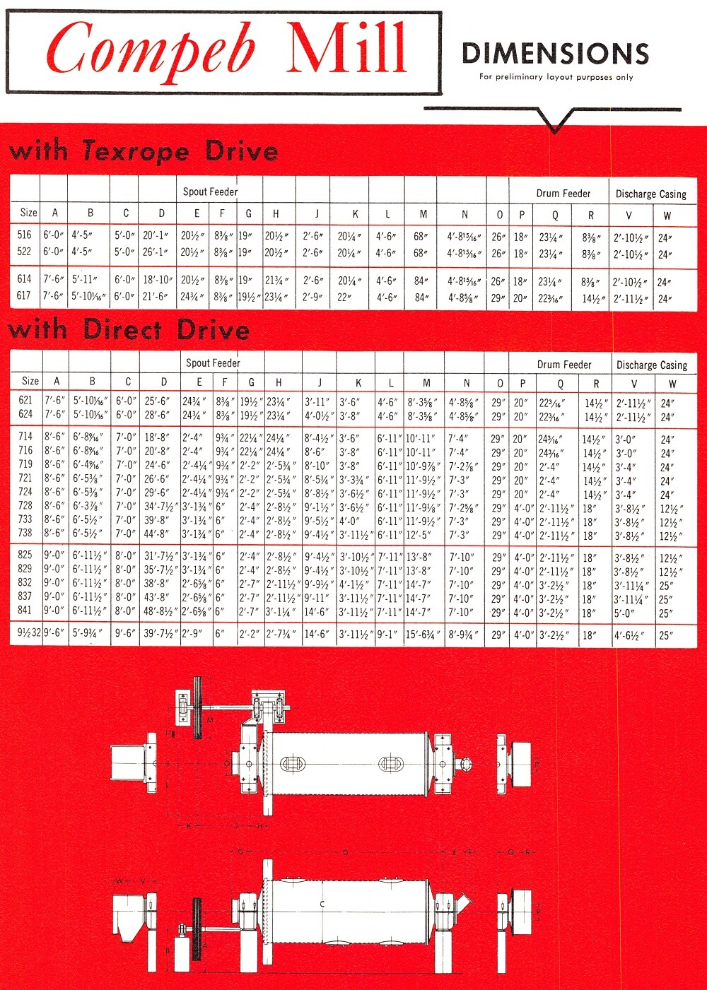
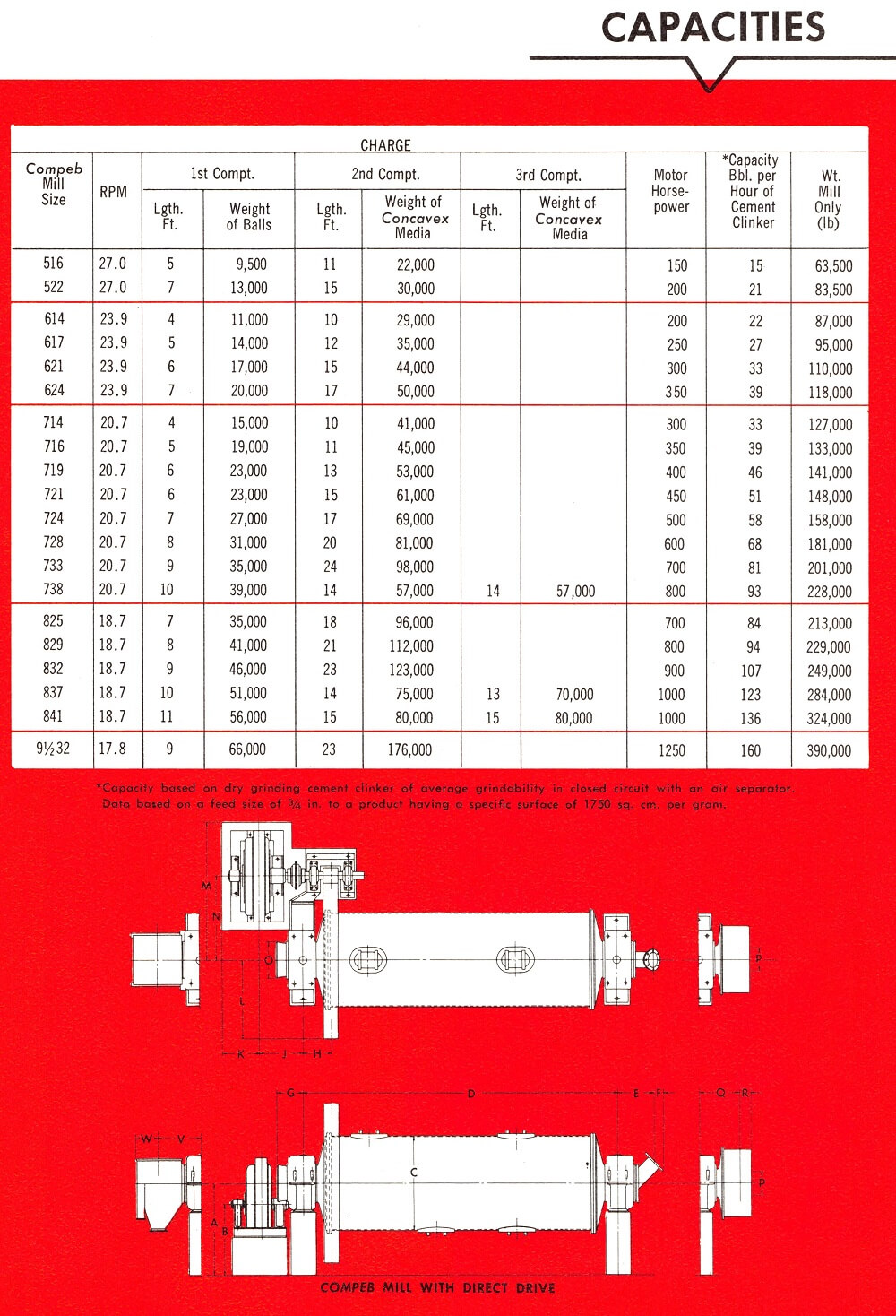
The Compeb mill is a type of ball mill designed to incorporate the Preliminator and Ballpeb mills in one relatively long shell. The initial or primary grinding compartment is lined with thick liners and carries large balls to accomplish the coarse grind. This primary compartment is followed by one or more secondary compartments which are provided with thinner lining and smaller grinding bodies. In the secondary compartments the product of the primary compartment is further reduced. Thus, the Compeb mill offers complete grinding from coarse feed to finished product in a single mill, either closed or open circuit.
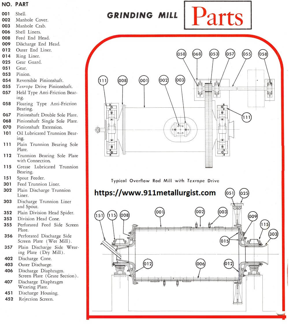
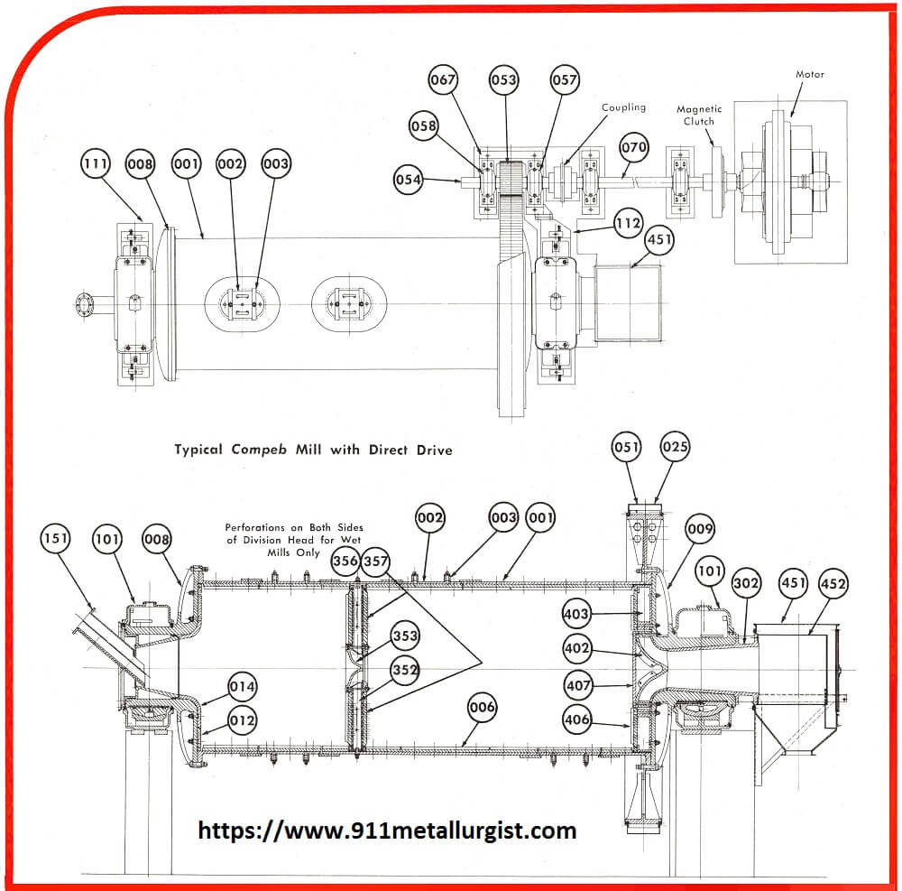
| NO. | PART |
| 001 | Shell. |
| 002 | Manhole Cover. |
| 003 | Manhole Crab. |
| 006 | Shell Liners. |
| 008 | Feed End Head. |
| 009 | Discharge End Head. |
| 012 | Outer End Liner. |
| 014 | Ring Liner. |
| 025 | Gear Guard. |
| 051 | Gear. |
| 053 | Pinion. |
| 054 | Reversible Pinionshaft. |
| 055 | Texrope Drive Pinionshaft. |
| 057 | Held Type Anti-Friction Bearing. |
| 058 | Floating Type Anti-Friction Bearing. |
| 067 | Pinionshaft Double Sole Plate. |
| 068 | Pinionshaft Single Sole Plate. |
| 070 | Pinionshaft Extension. |
| 101 | Oil Lubricated Trunnion Bearing. |
| 111 | Plain Trunnion Bearing Sole Plate. |
| 112 | Trunnion Bearing Sole Plate with Connection. |
| 115 | Grease Lubricated Trunnion Bearing. |
| 151 | Spout Feeder. |
| 301 | Feed Trunnion Liner. |
| 302 | Plain Discharge Trunnion Liner. |
| 303 | Discharge Trunnion Liner and Spout. |
| 352 | Plain Division Head Spider. |
| 353 | Division Head Cone. |
| 355 | Perforated Feed Side Screen Plate. |
| 356 | Perforated Discharge Side Screen Plate (Wet Mill). |
| 357 | Plain Discharge Side Wearing Plate (Dry Mill). |
| 402 | Discharge Cone. |
| 403 | Outer Discharge. |
| 406 | Discharge Diaphragm.
Screen Plate (Grate Section). |
| 407 | Discharge Diaphragm Wearing Plate. |
| 451 | Discharge Housing. |
| 452 | Rejection Screen. |
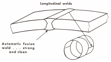 Our grinding mill shells are fabricated of rolled steel plate of a thickness sufficient to insure against distortion or failure in operation. Shells are of all-welded construction, welded one plate to a circle. Welding is done by an automatic welding process which assures full penetration and an even flow of weld rod for uniform strength. Comparable results are difficult to attain by hand welding methods.
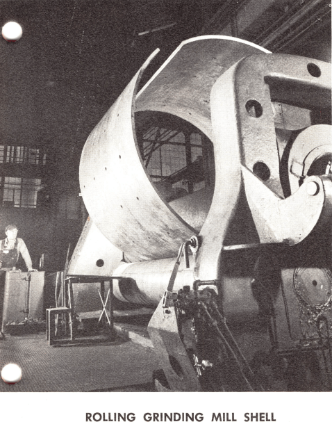
Today’s mill has unsurpassed facilities and personnel for the precision rolling of mill shells of consistently uniform diameter. Shells of true circular shape result in more uniform load on bearings, gears, drives, and permit better shell liner fit.
Grinding mill shells up to 26 feet in length are rolled from structural steel plate having approximately 55,000 psi tensile strength. Shells longer than 26 feet are rolled from carbon-silicon flange quality steel plate having approximately 60,000 psi tensile strength.
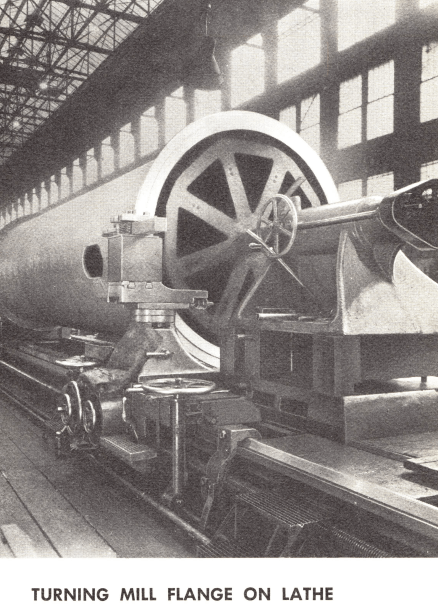
Flanges for mill shells are fabricated of rolled steel bars. Shells are welded integral to flanges, which are not machined until the entire welding operation on the shell, including the attachment of the manhole frames, has been completed. This machining operation (see illustration) assures that flange faces will be true with one another and that all parts will be in alignment.
When the nominal mill length exceeds twice the diameter, the entire mill is stress-relieved as a unit, prior to machining the flanges. Heat treatment relieves the residual stresses caused by rolling and welding . . . assures low bending stresses on long mills. Holes for shell liner bolts on all mills are drilled, not punched.
Manhole frames are oval shaped and fabricated of heavy steel plate welded to the shell. Manhole covers are of heavy steel plate and held in position by two crabs.
Allis-Chalmers grinding mill heads are cast of iron or steel and bolted to the shell flange with through bolts. These bolts are relieved of shear stress by a machined male and female joint between head and shell flange. All ball, rod and Preliminator mills, as well as the shorter Ballpeb and Compeb mills, have conical heads. The longer Ballpeb and Compeb mills have starfish heads (see illustration) which offer extra body and strength by means of a pattern of external braces.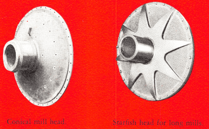
Whether of conical or starfish design, all heads and trunnions are cast integral. This makes the task of maintaining alignment of the mill much simpler than on mills where head and trunnion are two separate pieces. Trunnions are machined true with head fit. Thus, when the head is attached to the shell flange, the trunnion is concentric with the true horizontal axis of the mill.
The sturdy construction of these trunnion bearings assures more than adequate support for the revolving mass of the grinding mill. Bearings are designed with sufficiently low bearing pressure to assure long bearing life and trouble-free operation.
The use of babbitted bearing and the ball and socket design are two important features of these trunnion bearings. Experience has shown that there is less possibility of scouring the trunnion with babbitt than with any other material. The ball and socket design corrects for minor misalignment during mill erection
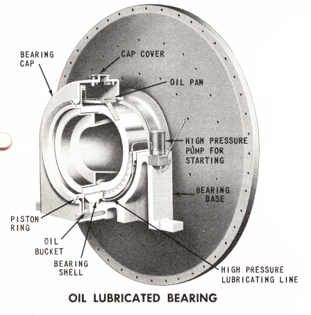
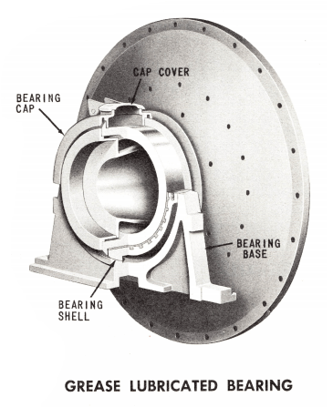
We offers large mills with oil lubricated trunnion bearings and small mills with grease bearings. Grease lubricated bearings have a large space within the bearing cap for grease. Oil lubricated bearings are lubricated with a positive internal oiling system or, if desired, an external system.
The cross-sections on the opposite page show the mechanism of the oil and grease lubricated bearings. In the oil type, an arm extends radially from the trunnion. A cup fixed to the outer end of this arm fills with oil from the reservoir, when the mill rotates, and is brought up and discharged onto the distributing pan, providing flood lubrication to the trunnion.
Experience has proved this an effective means to lubricate the bearing. Sufficient oil in the reservoir assures proper lubrication. The piston ring seal is an effective way of sealing the bearing from dirt while retaining the oil. Economy conscious operators are aware of the lower coefficient of friction attainable with oil lubrication.
A most important adjunct of the oil lubricated bearing is the manually operated high pressure pump used to “float” the mill before starting. Large, heavy mills “lock” when idle for long periods. This occurs when the idle load of the mill squeezes the oil out from between the trunnion and trunnion bearing. Floating the mill provides an oil film between metal parts, reduces friction before starting, and eliminates the high bearing wear incident to dry starting. A floated mill also reduces the high inrush of starting current — an important advantage often overlooked when considering the merits of various grinding mills.
If grease lubricated bearings are used, a mill can be floated by using a manually operated grease pump. Although this is optional equipment, the resultant advantages under starting conditions are the same.
Allis-Chalmers mills are provided with steel sole plates under the trunnion bearings. All mills have adjustable sole plates for lateral movement of the mill. On direct connected mills the sole plate at the gear end is extended for bolting to the steel pinionshaft sole plate.
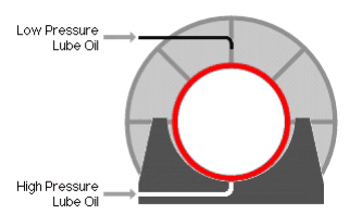
During normal operation, a film of lubricant separates trunnion from bearing. No metal to metal contact. |
After a short shut-down period the thickness of this protecting film of lubricant is reduced. |
After long shut-down, lubricant film is broken entirely. The result is damaging metal to ”metal contact between trunnion and bearing. |
Lubricant pump floats the mill before starting . . . re-establishes protecting film of. oil between trunnion and bearing. Starting torque is also reduced. |
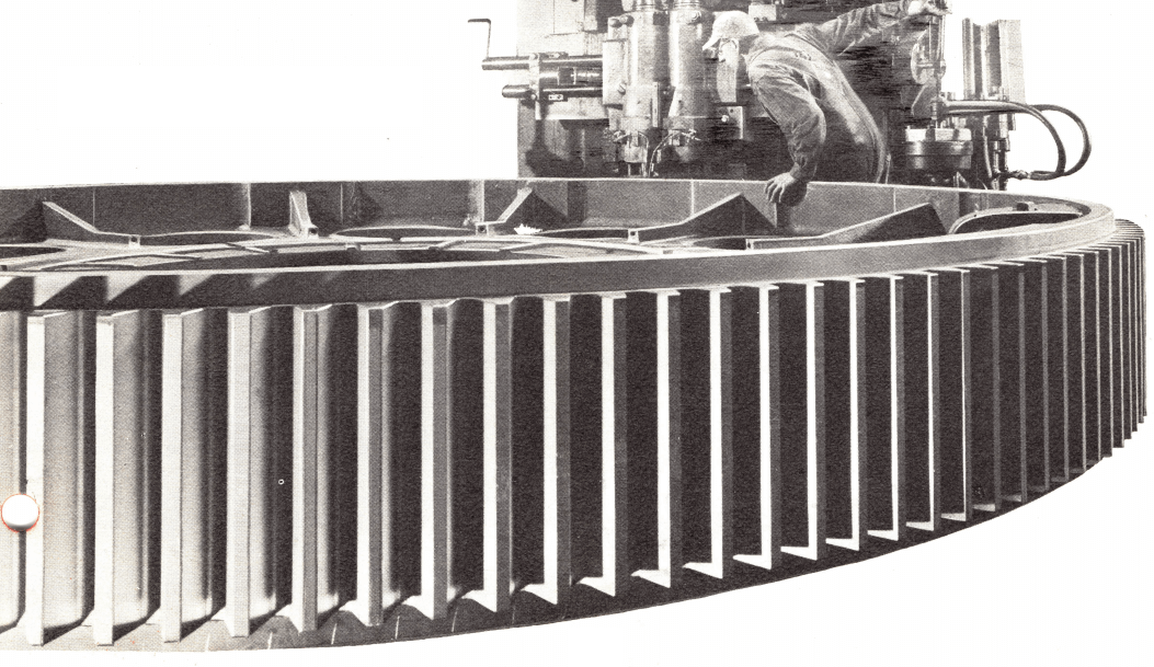
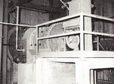
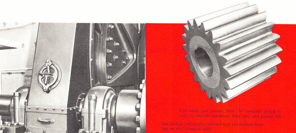
Today’s grinding mills are equipped with a new, improved 20° true involute cut tooth spur gear with short addendum gear and long addendum pinion. This design assures overlap of tooth contact by as much as 40 percent. The pinion teeth roll evenly on gear teeth, resulting in smooth, even transmission of power from pinion to gear. Comparative results have proved the 20° involute gear a most suitable gear for smooth mill operation and long gear life.
Gears for 3, 4 and 5 ft diameter mills are made of high quality cast iron with cut teeth; gears for the larger mills are made of either cast or welded steel, with cut teeth. The teeth are cut to a true form and then subjected to a thorough inspection of spacing and profile. The resultant uniformity of teeth assures long service.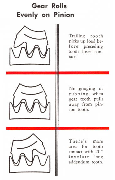
The mill’s main drive pinions are fabricated of forged steel and the teeth are carefully cut to assure smooth mating action with the main gear. Pinions meshing with steel gears are hardened to prolong their life.
Main gears are reversible and split in halves to permit easy removal and reversal. All main gears on direct driven dry grinding mills are manufactured with an extended flange on both sides of the teeth to provide a seat for the oil and dust seal which is a part of the gear guard and lubrication housing.
These rod and ball mills may be equipped with either herringbone or single helical gears. These are not recommended for Preliminator, Ballpeb or Compeb mills because the heat generated during dry grinding results in expansion problems.
Direct drive spur pinions are mounted on a short reversible stub pinionshaft which permits reversing the pinion without removing the pinion from the shaft. The pinionshaft
is keyseated for both spur pinion and coupling. For mills equipped with Texrope drive, pinionshafts are keyseated for pinion and Texrope sheave.
In all mill sizes, the pinionshafts are mounted in antifriction (roller) bearings which are considered superior to the babbitted sleeve type for these reasons: (1) Roller type bearings offer a decreased coefficient of friction. (2) Since the wear on an anti-friction bearing is negligible, the alignment of gear and pinion is maintained. (3) Antifriction bearings require minimum lubrication and provide excellent seals for keeping dust and dirt out of the bearing.
Wet grinding mills of 6 ft diameter and larger are fitted with semi-enclosed safety type guard. Preliminator, Ballpeb, Compeb, and dry grinding ball and rod mills have gear and pinion totally enclosed in a 360° steel plate lubrication housing.
The lubrication housing protects the gear and pinion from outside dust and dirt, materially lengthening the life of the gears by preventing unnecessary wear from abrasive dust. The housing is supplied with a heavy, long-life felt seal which bears against the extended flange of the gear and thus effectively seals the gearing from dirt.
The gear housing for Preliminator, Ballpeb and Compeb mills is provided with a plastic impregnated laminated fabric oiling pinion which is located in an oil reservoir in the bottom of the housing. This lubricating pinion mates with the main gear and, when the mill is rotating, transfers oil to the gear teeth which in turn lubricate the drive pinion.
For grinding mills of 250 hp or less, the Texrope V-belt drive has proven to be most satisfactory. Actually, the Texrope drive may be supplied for mills larger than 250 hp but the arrangement is usually undesirable because of the outboard bearing required by the motor and the large size of the driven sheave.
The Texrope drive employs a driven sheave mounted between the outboard bearing and one of the bearings adjacent to the pinion. The driving sheave is mounted directly on the motor shaft. Such a drive is flexible and economical both in initial cost and in maintenance, repair and replacement. A wound rotor motor is recommended for use with a Texrope drive.
This type of drive is used to permit the use of high speed motors or to meet special space requirements. Speed reducer drives offer a highly efficient and economical means of stepping down motor speeds. The speed reducer may be located either alongside or at the end of the mill.
Direct connected drives are ordinarily used on grinding mills requiring a drive larger than 250 hp. These mills employ slow speed synchronous or wound rotor motors coupled direct to the pinionshaft.
With either the direct connected or speed reducer drive, the gear is aligned with the pinion by means of a set screw adjustment on the main bearing sole plates. This adjustment can be made without disturbing the alignment of the motor and pinionshaft.
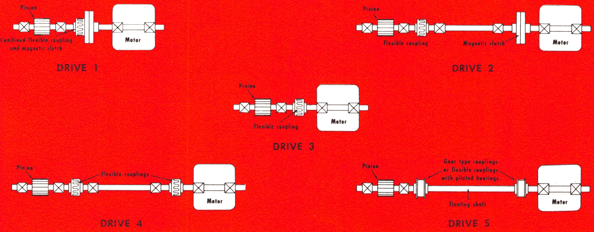
We offer several possible drives in its direct connected series. A mill can be provided with a low speed synchronous motor having torques of approximately 40% starting, 30% pull-in and 175% pull-out for use with a magnetic clutch. A magnetic clutch drive may involve a close coupled unit with two pinionshaft bearings and combination clutch-coupling (Drive 1), or four bearings with a clutch and flexible coupling (Drive 2). The use of a magnetic clutch permits the use of a reduced voltage starter to reduce the starting kva which would result when a full voltage starter is employed.
A magnetic clutch permits “floating” a synchronous motor on the line during mill shutdown to aid in power factor correction.
The most compact direct drive, where electrical conditions permit its use, is the direct connection of a high torque synchronous motor (approximately 160% starting, 140% pull-in and 225% pull-out) to the pinionshaft through a flexible coupling (Drive 3). When plant design makes it essential to locate the motor at a distance from the mill, the drive arrangement may be as shown in Drive 4 or 5.
In addition to the drives described above, we offer the synchronous-induction motor, which is wound so as to permit the use of a reduced voltage starter. This motor starts its operation as a wound rotor motor but reverts to a synchronous motor after it picks up speed and comes into step. This permits use of a synchronous motor with low starting current inrush and without magnetic clutch. This arrangement is used where a magnetic clutch is not desired and where electrical transmission line characteristics do not permit high starting kva.
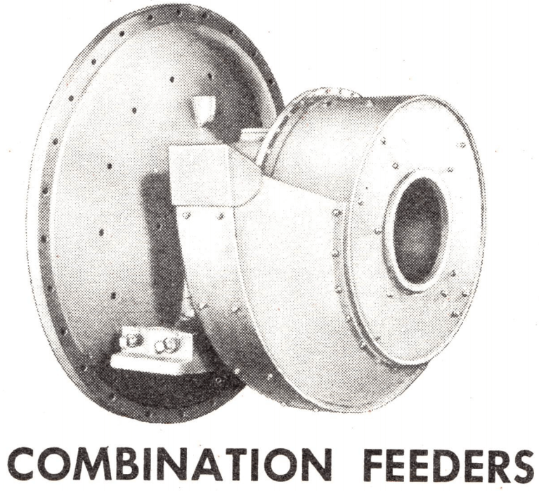
Grinding mills for the mining, cement and rock products industries may he furnished with or with-out mill feeders, as desired. Feed chutes can he any one of several types which convey the material into the mill. None of the feeders described here weigh or proportion materials fed to the mill. Weighing or proportioning feeders can he purchased from several manufacturers and many operators feel that a feeder which controls and records the feed rate is well worth the additional cost.
This feeder receives new feed through the orifice of the drum while the scoop lifts and returns the classifier sands. The drum opening also permits the charging of balls to the mill.
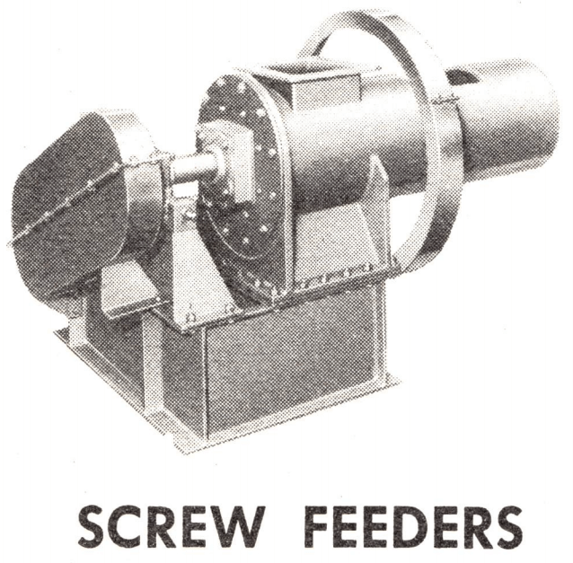
This type handles dry, dusty feed and is no .longer in general use. Screw feeders can be designed to feed material into the mill and, at the same time, effectively seal the trunnion opening. This is essential for grinding some materials in a controlled atmosphere, other than air. Screw feeders have individual motor drives.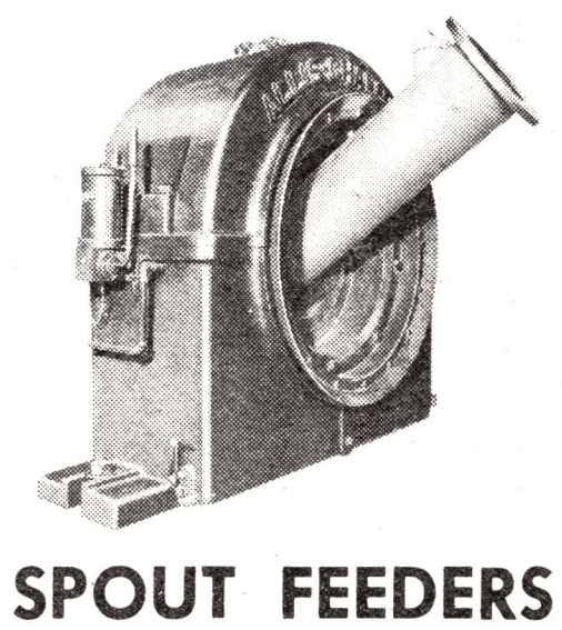
The spout feeder is the simplest of all feeders. It consists of a cylindrical spout or chute lined with either steel wearing plates or rubber lining. Spout feeders are used where the feed, plus the circulating load, if any, has sufficient elevation to be spouted directly through this feeder into the trunnion opening of the mill. Generally, the spout feeder can be used wherever a drum feeder is used. It has the advantage of permitting a constant flow of feed, resulting in higher capacity through the feeder. Most operators prefer the spout feeder because of its simple and inexpensive maintenance.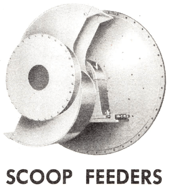
In closed circuit grinding, scoop feeders return classifier sands to the mill for regrinding. They may also be used to take initial feed and may be of either single or double scoop construction. The illustration above shows the double scoop type. The opening in the center is used to charge balls into the mill. Scoops are provided with replaceable wearing tips. 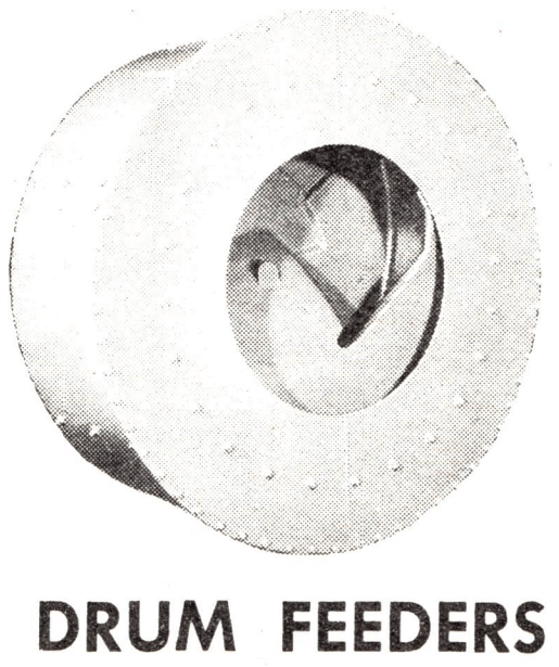
The drum feeder is the logical substitute for a spout feeder if the bin storage lacks sufficient headroom to spout the material successfully. This feeder consists of a steel plate drum or housing, a spiral made of high quality cast iron and suitable liner plates for the housing. If the material being ground is corrosive, the feeder may be constructed of stainless steel throughout.
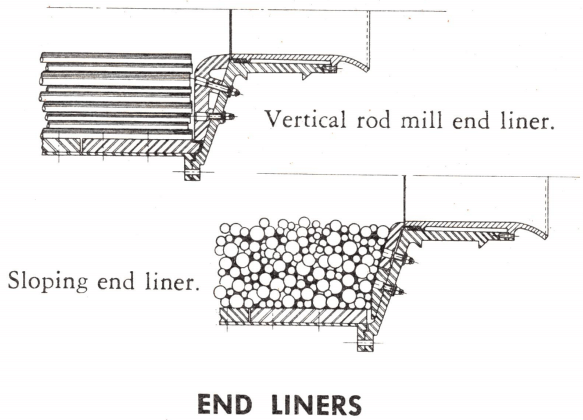
The overflow mill, used for wet grinding, is the simplest of the three basic mill designs. Pulp in overflow mills is discharged by displacement, the new feed to the mill displacing an equal volume of ground pulp.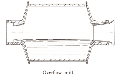
Since there is no appreciable pulp gradient within the mill, all the grinding media is surrounded by pulp to be ground. This cushioning by the pulp tends to reduce wear of grinding media and liners. The cost of metallic balls, rods and liners has risen steadily in the past decade and many operators have chosen the overflow mill to reduce their operating costs. Furthermore, the overflow mill does not have a diaphragm, component parts of which are more complex, expensive and short-lived than the comparable end liner in an overflow mill.
The capacity of the overflow mill is not as high as a diaphragm mill with the .same size grinding chamber. Power requirements per ton of material ground are substantially the same for either type mill.
Overflow mills have proven mo£t popular as secondary mills in a two-stage circuit, as employed in the mining industry. There are some operators who prefer the overflow mill for single stage closed circuit grinding of large feed.
 |
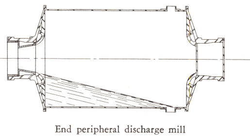 |
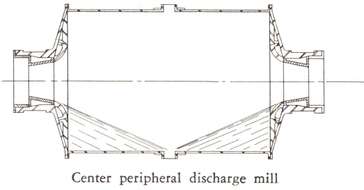
The peripheral discharge, as used in a rod mill, is a means of establishing a gradient within the mill without the use of a low-level diaphragm. This cannot be done in a ball mill unless a special division head is used.
Rod mills can be built as either end peripheral or center peripheral discharge types, the product from the center peripheral type being coarser.
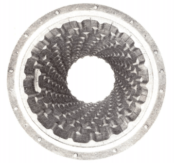
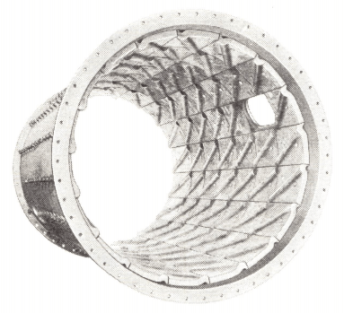
Occasionally, a multi-compartment mill is used with peripheral discharge openings following either the first or second compartments. A plain division head is used to retain the charge of balls or Concavex grinding media. Material is discharged and classified, the oversize returning to the (original) feed end of the mill and the fines being fed through the opposite end of the mill for further grinding.
 |
 |
 |
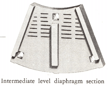 |
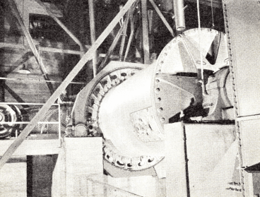
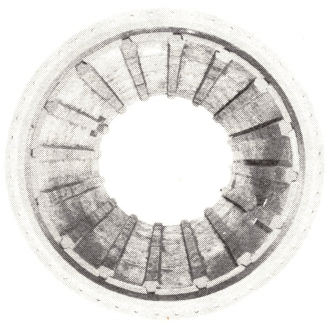
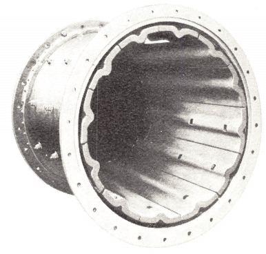
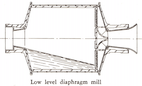
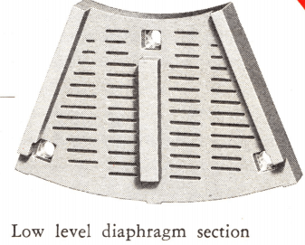
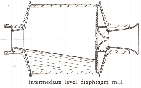
The discharge end of this mill is fitted with a diaphragm, i.e. a perforated steel plate placed approximately 6 in. from the discharge head. Lifters between this perforated plate and the mill head elevate the ground material and drop it on a discharge cone (see illustration) which directs the material into the trunnion and out of the mill.
The function of the diaphragm is to retain the grinding media and allow free passage of the wet pulp or dry material through the perforations. On starting, the pumping action of the diaphragm lifters establishes a gradient within the mill. For grinding dry materials a steep gradient is essential to move the material through the mill. In wet grinding this gradient results in a short retention time per particle, with the advantage of less overgrinding.
Diaphragm mills have been designed with two variations, Low-Level and Intermediate Level types. In the first, the diaphragm sections are perforated down to the periphery of the mill, which establishes the maximum gradient within the mill. The Intermediate Level diaphragm mill establishes a gradient which is less steep by maintaining a pool of pulp at the discharge end. Diaphragm perforations are held to within 10 to 18 in. (depending on the mill diameter) of the periphery. Size for size, the Intermediate Level mill offers a capacity greater than the Overflow mill and less than the Low-Level diaphragm mill.
Use of the diaphragm is almost universal with ball mills in the cement and rock products industries because of the many dry grinding operations in this field. It is optional on ball mills in the mining industry, but not recommended for rod mills. Diaphragms are standard equipment for Preliminator, Ballpeb and Compeb mills.
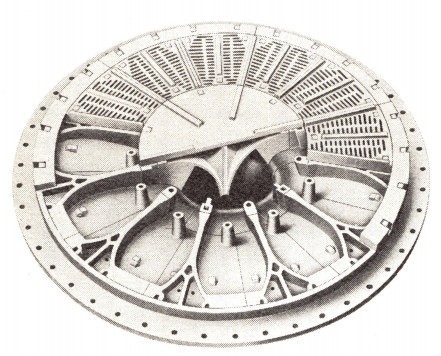
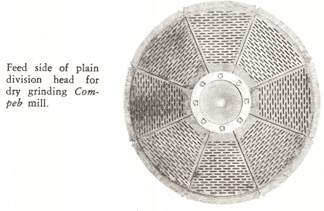
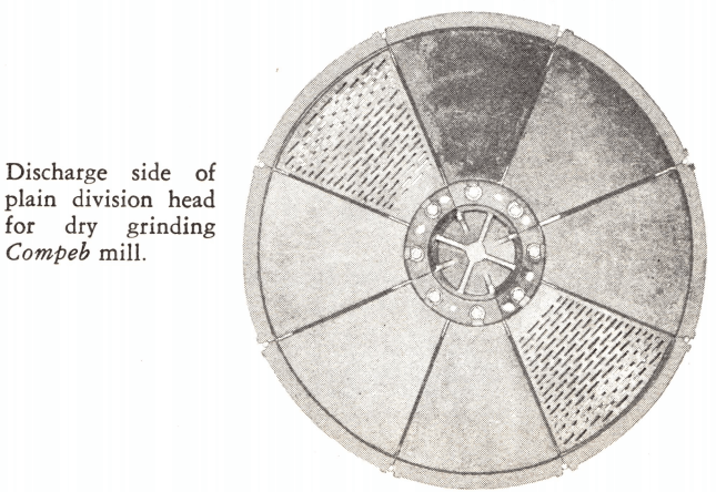
Division heads are used in Compeb mills to divide the mill into two or three compartments . . . and in long Ballpeb mills to divide it into two compartments. Plain division heads are made in both dry and wet types. The dry type have screen plates on the feed side and solid wearing plates on the discharge side. Material in the first compartment cannot flush through into the second compartment, but must be picked up by wings between the screen and the solid side and discharged into a center cone which funnels the partially ground material into the succeeding compartment.
Wet plain division heads have screen plates on both sides of the spider which allow the pulp to maintain a more uniform gradient throughout the mill.
 |
 |
 Rod Mills
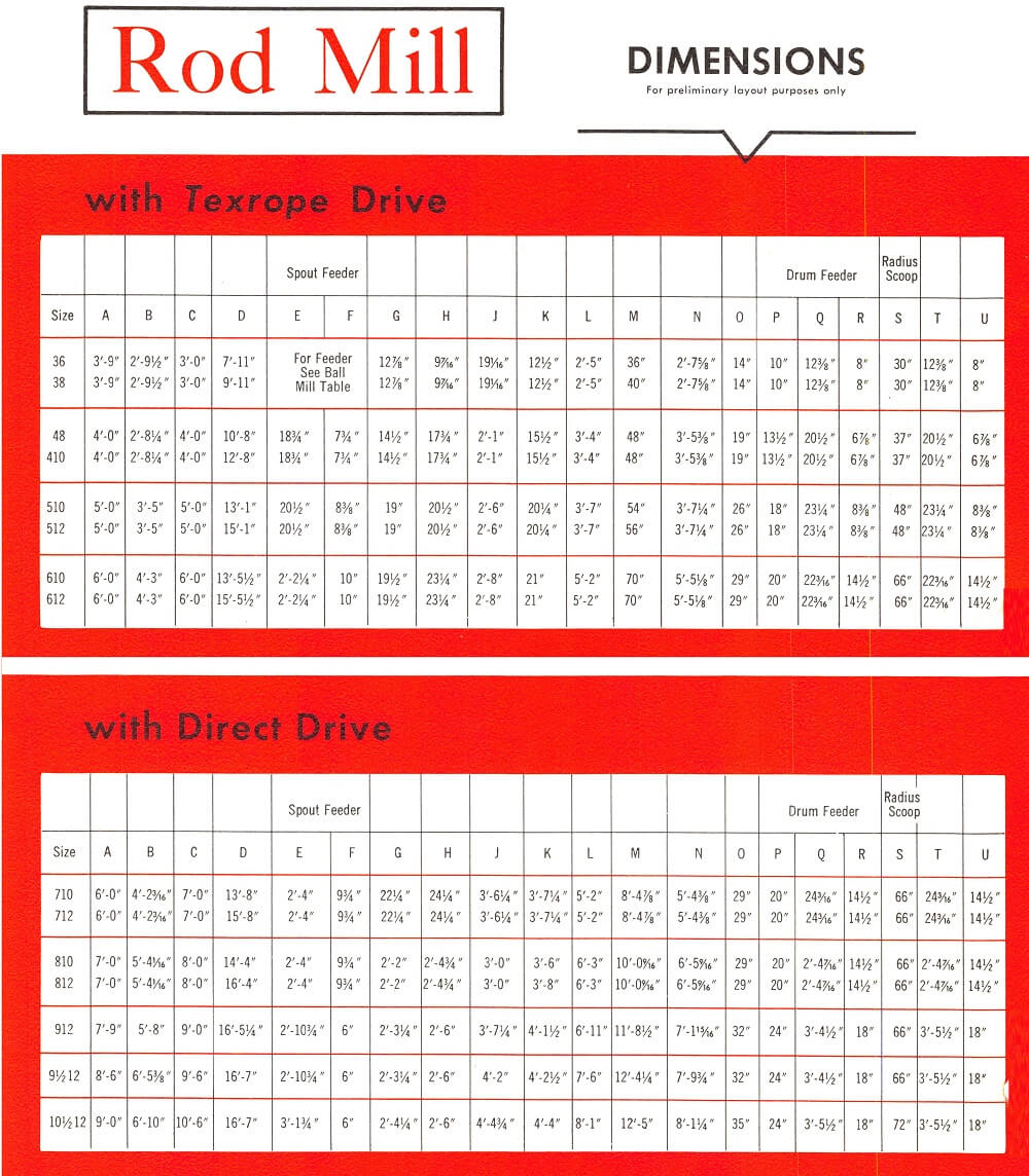
A reproduction of Allis-Chalmers 1951 “Grinding Mills: For the rock products, cement, chemical and mining industries.”
Grinding in small plants, as in larger installations, has proven to be the most costly of all unit operations from both capital and operating standpoints. Therefore, grinding deserves the most scrutiny of all operations during the design procedure.
A recent survey by a major grinding mill manufacturer reveals that more than 80 autogenous or semi-autogenous mills having between 100 and 1,000 connected horsepower have been sold during the last twenty years. Obviously, this type of grinding approach cannot be arbitrarily excluded from consideration in a small installation.
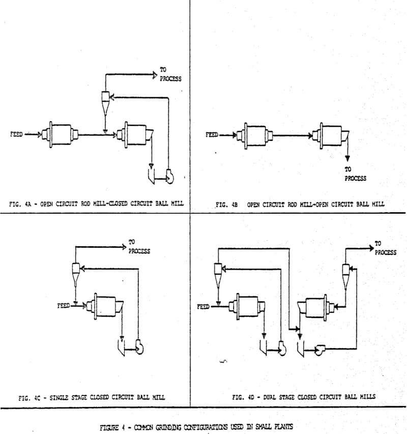
Usually the grinding system in a modern small concentrator consists of one of the following configurations:
Open Circuit Rod Mill-Closed Circuit Ball Mill
This configuration has proven in the past to be a most reliable system due to the fact that rod mills are not particularly susceptible to variations in feed size. However, the necessity to procure grinding rods may limit the usefulness of this approach in certain locations.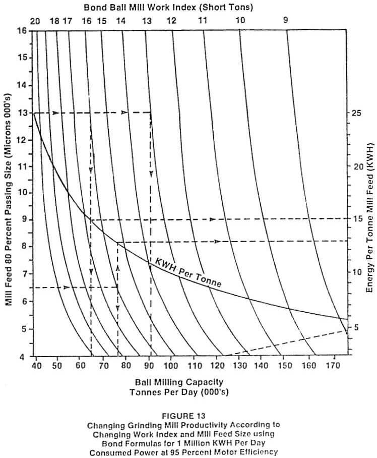
Open Circuit Rod Mill-Open Circuit Ball Mill
This configuration is employed when it is desired to produce a final ground product having a very high pulp density. This situation can be useful for various types of leaching circuits but does not normally apply to flotation concentrators.
Single Stage Ball Mill
Single stage ball milling has proven to be very popular in recent years. Both overflow and diaphragm (grate) ball mills have been used as single stage grinding units. If the feed to such a system can be top size limited, for example by the use of closed circuit crushing, this type of installation can prove to be the most efficient from both the capital and operating standpoint.
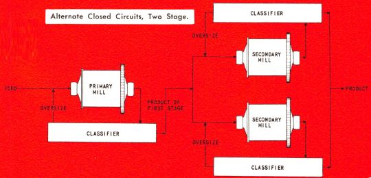
Double Stage Ball Mills
Occasionally, the liberation requirement for an ore requires very fine primary grinding. Usually, the most expeditious way to accomplish this objective is by double stage ball milling. Both mills are usually operated in closed circuit with separate classifiers.
In smaller plants, grinding mill drives should be as simple as possible. The drive train usually recommended consists of a slow speed motor which drives the mill pinion through an air clutch. This slow speed motor system tends to be slightly more expensive than the alternate drive train consisting of a high speed motor and speed reducer but the ease of maintenance and the simplicity of the slow speed system offset the additional cost.
The mill feed belt should be equipped with a weightometer having cumulative and instantaneous tonnage indicators visible both locally and in the control room. In recent years, load cell weightometers have proven to be very reliable and are relatively simple to calibrate. The digital readouts supplied with load cell weightometers have proven to be rugged and reliable.
The mill dilution water stream should be visible and its control valve should be readily accessable. A simple water proportioning valve is sometimes recommended to give semiautomatic regulation to mill dilution water.
Mill sizing for most grinding installations is usually arrived at through calculations involving required throughput, ore work index estimates, and feed and product size-distribution requirements. This information is then tempered with experience to arrive at actual mill size recommendations. In the case of small concentrators located in remote areas, the method and route of delivery to the plant site must also be considered. There are cases on record where mill diameter has been dictated by railroad tunnel dimensions and mill length by the presence of severe switchbacks and small bridges over precipitous canyons.
Ball mills should be equipped with trommels constructed of punched plate or screen cloth and are usually fabricated with a reverse internal spiral. The trash rejected by the trommel is normally collected in a forklift box.
Ball charging should be arranged for the convenience of the operator. In remote areas, grinding balls are usually received in welded 55 gallon drums each of which weighs between 500 and 600 kilograms. Suitable handling equipment for grinding media must be supplied by the design engineer. It should be noted that the ability to assemble a graded ball charge at the mill site prior to startup may not be possible. An initial properly-graded ball charge should be purchased from capital funds and included in the grinding area unit cost.
Rubber liners represent a significant cost saving for smaller installations. This type of liner, although possibly contributing to somewhat less efficient power utilization, is very simple to install with unskilled personnel as contrasted to conventional cast metal liners.
The necessity for regrinding is usually determined by laboratory or pilot-scale test work. If a project is to be designed from bench scale work only it is prudent to include a regrind mill in the circuit even though laboratory work does not indicate the necessity for this unit operation. Regrind mills are difficult to size since work index data are not generally available. Therefore, the design engineer should be generous when sizing a regrinding installation.
There is a tendency to employ spent grinding media from the primary grinding installation as media for the regrind mill. It is much better to use small-diameter properly-sized grinding media for regrinding since the utilization of spent media tends to reduce efficiency.
Regrind mills tend to be rather difficult to reline since they are usually of small diameter. Rubber regrind mill liners are an obvious solution and have found application in many installations. Of course, the rubber composition employed must be compatible with the flotation reagents associated with the regrind mill feed.