


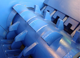
The standard spring roll crusher have two horizontally mounted cylinders. The set is determined by spacing pieces (shims) which cause the spring-loaded roll to be held back on its sliding mounting from the solidly mounted roll. Modern rolls have both cylinders positively driven by separate motors, so that they rotate inward and downward. Rolls crush by nipping the feed between the approaching roller faces and it is essential that the entering material is seized and drawn down.

One method used to calculate maximum size of feed is based on the angular relations shown in Fig. 26. Tan B is the coefficient of friction (usually taken as 0.3); A is the angle of nip, or wedge angle below which a particle is seized, and above which it skids; R is the radius of each roll. 2X is the thickness of the particle which can be gripped at zero setting, and S is the set, or distance apart, of the roll faces at their nearest point of approach.


The method of feeding is important. Unless the entering ore is spread evenly over the whole width of the rolls, partial wear occurs, causing the surfaces to become grooved or flanged. A heavy-duty crushing rolls incorporate a “fleeting” mechanism which causes one cylinder to move to and fro on its axis, thus reducing this type of wear. A good practical rule is to arrange the feed so that some ore falls outside the crushing area at each end. This helps to even wear over the full width of each roll. Another is to raise the feeding device so that ore arrives on the rotating surfaces at their peripheral speed. This gives the best conditions for seizure. Rolls can only work as “arrested” crushers if lightly fed, because the breaking ore swells in volume as voids are produced, at the same time as the particles fall into a more restricted space. If not “starvation” fed, rolls are choke-crushers, ore grinding on ore. Unless rolls of very large diameter are used, the angle of nip limits reduction ratio, so that a flow-line may require coarse-crushing rolls to be followed by fine-crushing rolls. Although the floating roll is only supposed to yield to an uncrushable body, the choked packing of ore in the crushing throat sets up so much pressure that the springs are usually “on the work” during crushing, and a moderate proportion of unfinished material is let through. For this reason, rolls should be worked in closed circuit with screens wherever control of maximum particle size leaving the crusher is important.
Roll crushing of the sledging type have a crushing action unlike that of any of the machines thus far described. Moreover, the actions of the single and double-roll forms of this type are dissimilar, at least in the relative importance of impact and sledging action. Both types employ a combination of these two actions but in a reversed order of efficacy. As a sledging blow transfers a large part of its force by impact, it may seem anomalous to attempt to differentiate these two terms; nevertheless there is a convenient distinction between them as they apply to the action of crushing machines. Impact crushing is customarily taken to mean the breaking of a piece of material by a sharp blow, delivered with sufficient force to shatter the piece while it is in a free position, i.e., not restricted from moving away from the blow other than by its own inertia. Sledging, while the blow may be just as violent as the impact blow, is a stroke delivered against the material while it is prevented from moving away from the applied force by reason of being in contact with an opposing crushing surface, either fixed or moving.
Crushing rolls might, logically, include roll crushers of the sledging type, the name, by popular usage, is restricted to the double-roll machine (with either smooth or corrugated shells) which crushes entirely by pressure between the surfaces of the roll faces. The sledging type of either single or double-roll arrangement is usually differentiated by such titles as “roll crusher” or “sledging rolls.” The only point of similarity in the actions of the crushing rolls and the gyratory and jaw types is that both do their crushing by pressure. As contrasted to the action of gyratory and jaw types, rolls have a continuous “one-bite” action; once a particle of material is firmly gripped, it is drawn down between the converging shell faces in one quick, continuous “squeeze,” until the discharge point is reached. Another point of difference is that the rolls do not rely upon gravity to work the material down through the crushing zone; the action is a forced, mechanical one. Still another difference between the types is that, in the crushing rolls, there is no “close-side” and “open-side” discharge setting; the distance between roll faces on a line between the two shaft centres establishes the discharge opening, which remains unchanged during normal operation.
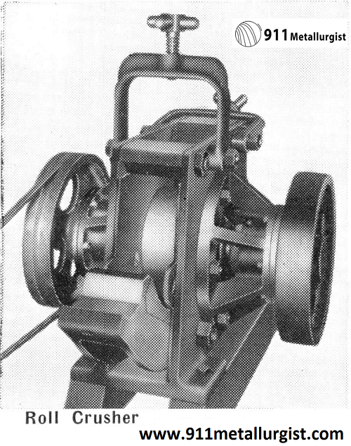
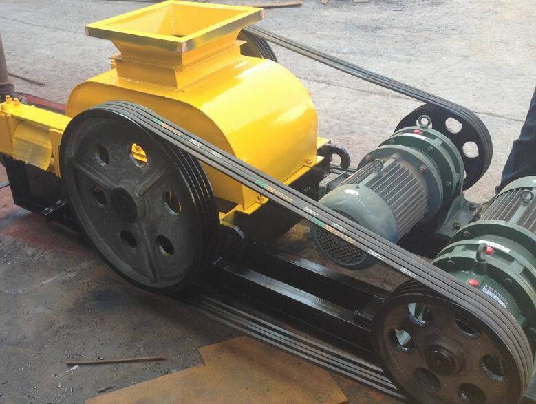
Mechanically, a pair of crushing rolls is a simple machine. Below are drawings that show all of the essential details of construction of a heavy-duty machine.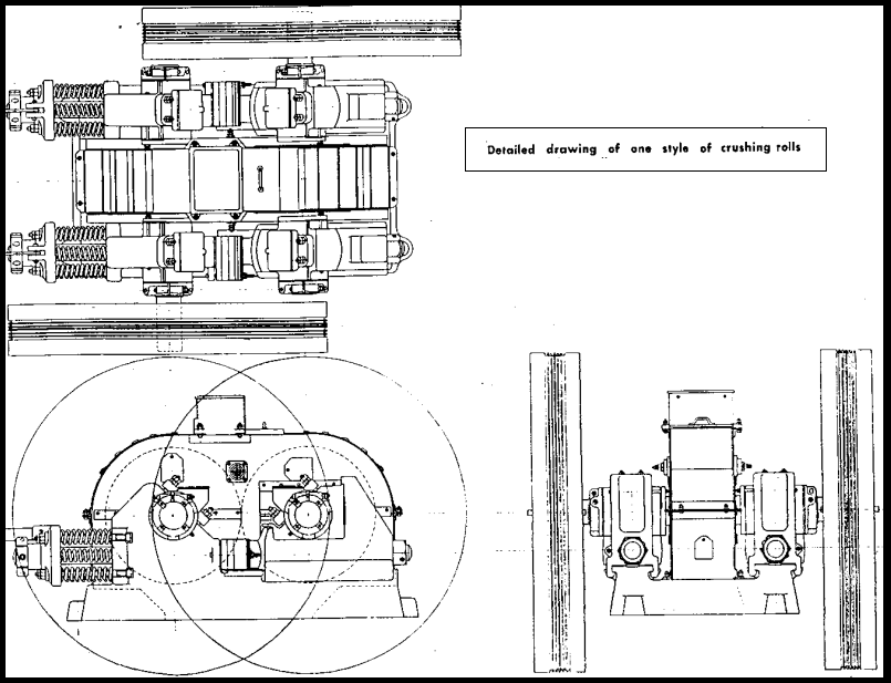
A heavy and rigid cast-iron frame supports the two-roll assemblies, each of which comprises a shaft, a roll centre, and a shell of wear-resisting metal, such as high-carbon steel, or manganese steel. Each roll is independently driven by a flywheel type, flat-belt pulley, or V-belt sheave. One of the two pairs of bearings is arranged to slide horizontally on the side frames.
These movable bearings are spring-loaded to provide a safety relief for excessive pressures, such as are caused by tramp iron, etc. They are drawn up against locating shims which establish the spacing between roll faces (discharge setting), and are held in that position by the springs, which are pre-set to the working pressure for which the particular machine is designed. This working pressure may vary from as low as 90 kilo per linear centimetre of roll face, for light-duty rolls, to as high as 5.3 tonne per centimetre of roll face for extra-heavy-duty rolls.
 So long as flat belts were the established driving medium, it was customary to equip the fixed roll with a large pulley, and the movable or spring roll with a smaller one generally one-half the diameter of the large one. The large pulley was designed to carry the full amount of power needed to drive both rolls, which of course relegated the smaller one to the status of an idling pulley; its sole purpose was to bring the spring roll up to speed, and to maintain that speed during idling periods.
There was a logical purpose behind this arrangement. Because of the variables involved, it would be the exception, rather than the rule, if both roll faces ran at exactly the same speed under no-load conditions, and if this “slip” between faces continued when the rolls were loaded, wear on the shell faces would be greatly accelerated. The large-and- small pulley set-up permits the material to “gear” the shell faces together so that the speeds are the same, and any compensation that might be required in surface speeds is taken care of by belt slippage on the small pulley.
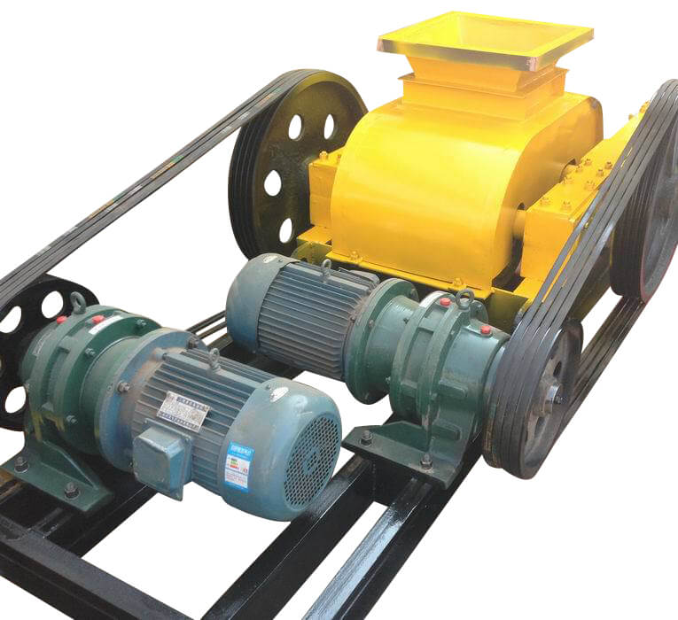
When the multiple V-belt drive came into its own, and line-shaft transmission was replaced by individual motor drives, an improved driving arrangement for crushing rolls was developed.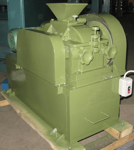 V-belt sheaves of equal size were installed on both rolls, and the load was divided between two motors. With this system, any speed compensation which may be required is taken care of automatically by increased slip of whichever motor happens to be driving the roll with highest no-load peripheral speed.
Although crushing rolls fitted with corrugated shells have been used in some special applications for secondary crushing, they are essentially a fine-reduction crusher, and as such are always fitted with smooth-face shells. The maximum one-way dimension of feed size is established by that point at which the rolls will nip the feed. This, in turn, depends upon the coefficient of friction of the material, the diameter of the rolls, and the spacing between roll faces.
The diagram in Figure #3 shows the method used in calculating maximum feed size for any diameter of rolls; the accompanying table gives a listing of feed sizes for standard diameters. These figures are based upon zero roll spacing; therefore the distance between faces (i.e., the discharge spacing to be used) should be added to them to obtain the maximum feed size for any combination of roll diameter and setting. The calculations are predicated on a coefficient of friction of 0.3, which is safe for most materials, provided that the surface speed of the rolls is not too high.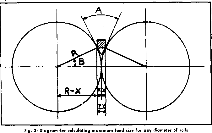

The theoretical capacity of crushing rolls is arrived at simply by calculating the volume of the ribbon whose cross section is the area of the discharge opening, and whose length is the peripheral speed of the roll faces per unit of time. The formula, for material weighing 100 lb per ft3, is:
D x W x S /48 = TPH
Where:
This “full-ribbon” formula gives results which cannot be achieved in practice, except for special conditions of choke-feed on small material, where the rolls are forced apart by pressure of the material, thereby thickening the ribbon. For the more usual condition of regulated feed the results must be divided by a service factor to arrive at a conservative estimate of capacity. For heavy-duty rolls, a factor of 3 may be used; for light and medium-duty rolls, it is safer to divide by 4. These compensating factors may be inserted in the formula by using divisors of 144 and 192, respectively, instead of the regular divisor of 48.
Several factors enter into the determination of the maximum practicable surface speed of crushing rolls. These are:
The ways in which these factors influence roll speeds may be stated briefly as follows:
A certain amount of momentary slip of the individual particles of material will occur in any set of rolls, regardless of diameter or size of feed. This slip is due primarily to the difference in velocity of the particles and the roll faces at the moment of nip; the obvious tendency is for the slip to increase as the surface speed increases; also, it will increase as the angle of nip is increased. Hence, to hold the slip within reasonable limits, the angle of nip must be decreased as the speed is increased.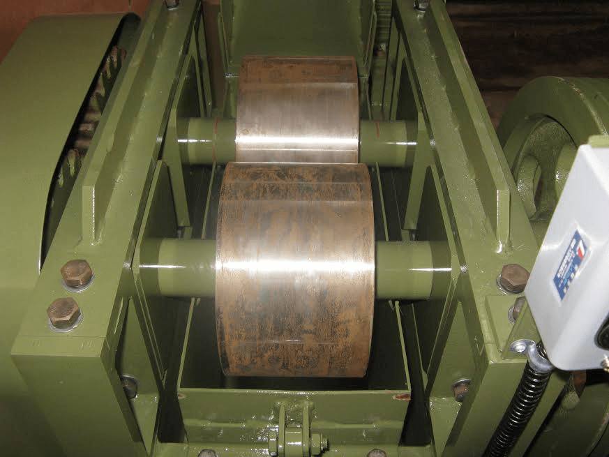
The feed size being a fixed quantity, for any given application, the only way to decrease nip angle is to increase the roll diameter.
Shocks incidental to shattering the particles of any given size of feed increase with speed, and with the crushing strength of the material. Large diameter rolls, because of their greater mass, can absorb these shocks better than smaller, lighter rolls; therefore they are more suited to high speed operation. It is equally clear that high-spring-pressure, heavy-duty rolls are better fitted, because of their superior shock-absorbing capabilities, to stand up to high speed crushing than rolls of more modest proportions.
Lastly, we have the character of the material to consider; that is, its resistance to crushing and its coefficient of friction.- Except for occasional special cases the latter is not apt to diverge greatly from the normal; therefore it does not as a rule inject any special complication into the problem. On the other hand, hardness and toughness do vary widely and must be taken into consideration in selecting the proper size and class of rolls.
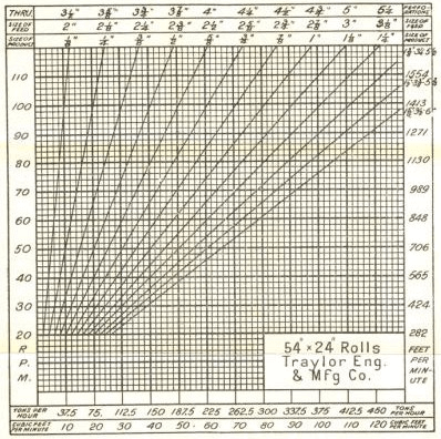
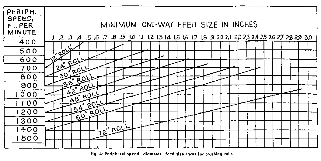
It would be exceedingly difficult, if not impossible, to incorporate al) of these variables into one comprehensive chart or formula. It can, however, be done for one type or duty-class of rolls if we assume a reasonably uniform coefficient of friction and base our values, for safety’s sake, on hard rock. Such a chart is shown in Figure #4. This chart was prepared for rolls of the heavy-duty class, with spring pressures in the approximate range of 5 to 8 tons per in. of face. Extra-heavy rolls may be run at somewhat higher speeds than indicated by the values given, unless the rock is extremely hard. Rolls of the class for which the chart was prepared may be run at higher than indicated speeds if the material is soft and friable. Light-duty rolls, on the other hand, should not be run at higher than indicated speeds on soft rock, and should be run somewhat slower on medium hard material. Light-duty rolls should not under any conditions be used for crushing hard rock or ore.
The chart above may be used in another way, by adhering to the values given for speed VS feed size, and selecting the class of rolls to suit the crushing characteristics of the material.
A great deal has been written, and said, about the limitations of the crushing rolls in the matter of reduction ratio, and there has been a tendency to pin the machine as a class down rather definitely to fixed maximums, regardless of any variables in conditions and characteristics of the materials to be crushed. For many years apparently by virtue of general consensus. It has not been deemed advisable to exceed a ratio of reduction of 4:1, and seldom was any exception noted in stating this rule.
The permissible or advisable reduction ratio for crushing rolls is subject to variation, just as it is in the other types of crushers. Light rolls are not capable of handling reductions as large as those which can be successfully performed in heavy machines. For a given size of feed, the large-diameter rolls will successfully handle higher reductions than will rolls of smaller diameter. And, for any particular machine, the permissible reduction ratio will vary inversely with the hardness or toughness of the rock.
The quality of product required has an important bearing upon the advisable reduction ratio. The way in which the crushing rolls perform their work, i. e., the continuous “follow-through,” once they have gripped the material, tends to create a “choke” condition in the discharge zone; a condition which would obviously be accentuated as the reduction ratio is increased. Inasmuch as such a condition promotes production of fines, it follows that a high reduction is undesirable if minimum fines are a requirement. For most commercial crushing plant applications it is advisable to hold the ratio within 3:1, rather than 4:1.
On the other hand, if the rolls are being used to prepare feed for fine- grinding units, fines are helpful rather than harmful. For such applications the permissible reduction is established by the ability of the individual machine to handle the job. Reductions of G or 7 to 1 are not uncommon for such operations utilizing heavy-duty rolls. Higher reductions than this are being performed in closed-circuit operations, running the rolls with a heavy choke-feed and a high circulating load. Such a performance, it should be stated, can only be economically performed on soft rock or ore.
The power required to drive crushing rolls varies with the hardness of the material, capacity, and ratio of reduction. On hard material the , power consumption, for a reduction ’ ratio of 4:1, will average approximately one horsepower-hour per ton of hourly output; for example, a ma-chine producing 50 TPH, handling 2″ feed, and set to 0.5″ discharge spacing, will require approximately 50 HP drive it. For soft, friable material this figure may be reduced as much as 50%. The power will vary approximately in direct relation to the reduction ratio.
The character of product delivered by crushing rolls may vary quite widely” on the same material. It was mentioned that a low reduction ratio is advisable if a minimum percentage of fines is desired. A light feed, i.e., a low rate of feed, will usually result in a cleaner product because the material does not become so closely packed in the choke-zone. Conversely, a choke-feed promotes production of fines; the rock is crowded into the choke-zone so rapidly that voids are eliminated, and the normal operating condition in this zone amounts to what in a jaw or gyratory crusher would be a full-choke. In the rolls it is relieved by the movement of the spring roll, which crowds back against the spring pressure when the unit pressure in the crushing zone exceeds the pre-set working pressure of the springs. Heavy-duty rolls can be operated in this way with good results, especially when run with high circulating loads in closed circuit with screens.
The tendency of rolls to create a packed condition in the choke-zone may sometimes have an unfavourable effect on the product. If the material is both soft and adhesive it may be discharged in cakes, which are sometimes quite hard and difficult to dis-integrate in other apparatus. Caking can be minimized by using a low ratio of reduction per stage, and a regulated feed to avoid excessive packing.
Some materials, notably, those of sedimentary origin, contain numerous parallel cleavage lines. Such materials are almost certain to “flake” in crushing rolls; that is, the product will contain a sizeable proportion of flat spalls. While this is of no particular moment in some products, ‘it is a serious detriment in others, such as concrete sand for example. When a cubical product is essential, and rolls are in all other respects suitable for the proposed application, laboratory or field tests should be run on the material to determine if the roils will turn out such a product.
Although a portion of the field formerly dominated by crushing roils has been pre-empted by newer machines of other types, there are a number of applications for which the rolls are eminently adapted. There is a gap, for example, between the economical product ranges of the gyratory fine crusher, on the one hand, and the ball mill or rod mill, on the other, which the rolls fill effectively. They are used for making granules and grits, and have been successfully applied to the production of manufactured sand for concrete aggregates.
 Although rolls never attained any great degree of popularity in the commercial crushed stone industry, a number of sets are being used for low reduction ratio re-crushing in stone and gravel plants. In this application they are quite successful. They are also well adapted by virtue of their forced-feed action to the handling of soft” and sticky materials, such as rock asphalt, although as has been noted, some materials of thus nature will cake in the rolls.
It is in the realm of ore dressing that crushing rolls found their greatest field of application, and, although a portion of this field has been taken over by the modern high-speed gyratory crusher, and some of it eliminated by changing methods in concentration practice, a large number of roils are still in active service in ore dressing mills throughout the world. Some experienced operators favor them in preference to any other type of crusher for the final crushing stage ahead of fine-grinding ball mills, as one example. They are also used in many mills to prepare the ore for coarse concentration, prior to further grinding for flotation or other recovery processes. Crushing rolls require a certain amount of skill and experience to obtain the best and most economical performance from them, and the mining man has learned through his years of experience how to operate them and care for them.
Except, perhaps, for the occasional low-capacity speciality application, the economical limit of product size for crushing rolls is about No. 16 mesh on soft and medium rock, and No. 8 or 10 mesh on harder material. They cannot compete with the hammermill on non-abrasive stone, but they will handle hard and abrasive materials a field from which the hammermill is excluded because of prohibitive maintenance.
Both single and double-roll crushers have been extensively developed for crushing coal, coke, shale and similar soft and friable materials. These machines resemble in general form the roll crushers we have described, but they are of course much lighter, and their mechanical details are correspondingly simplified. Instead of the knob-like teeth used on the stone-breaking rolls, these coal crushers are usually fitted with spike-shaped teeth, and the action has more of a tearing nature rather than the heavy slugging and sledging.
To simplify the drive, double-roll coal crushers are usually geared together, which works out quite satisfactorily because the shocks in machines of this type are light, as compared to those in stone-breaking rolls. This same practice, incidentally, was followed in the earlier, and lighter, rolls used on stone and ore; it is not used in any of the present-day heavy-duty double rolls. Single-roll coal crushers are driven by the same gear-and-pinion arrangement used in single-roll stone crushers. Peripheral speeds range from about 400 to 800 ft/min , the double-rolls usually running at higher speeds than the single-roll machine.
It is generally considered that Roll Crushers are specially adapted for intermediate crushing, taking a product from rock- breakers with a maximum diameter of from ¾ inch to 1½ inches, and reducing it to a size passing through a screen of 12 or 16 meshes to the square inch. Finer crushing, however, is often carried out. The exact limit at which rolls cease to be economical machines is still a matter of doubt. Like other dry crushing machines, they are better suited for soft friable material than for either hard or caking (clayey) ores.
Rolls are cylinders, between two of which pieces of ore are drawn and crushed by compression. They are placed with their faces a short distance apart, this distance varying with the degree of fineness to which the ore must be reduced. The main driving power is applied to the shaft of only one roll, by means of belt pulleys, the other roll being driven only with sufficient force to ensure that the rollers will always take hold of the ore, and also to keep them in motion when no ore is passing between them.
In the older forms, tooth-gearing was used instead of belt pulleys for the application of the power, and the two rolls were compelled to revolve at an equal rate of speed by gear-wheels, connecting together, placed on the axles. The advantages of belted rolls are, that a higher speed can be easily attained, and also that if the rolls were to become jammed from any cause, the belts would slip or be thrown off, while the tooth-gearing would be broken. Geared rolls, however, are still largely used for coarse crushing. The rolls have crushing tires made of steel or of chilled iron. Chilled iron is much cheaper, but the wearing of the faces is more rapid and less uniform than in the case of steel rolls. Emery wheels are used for levelling the unevenly worn faces of the rolls. The crushing tires can be taken off and replaced when they are worn out. In some rolls the crushing strain is taken up by powerful springs, which press the rolls towards one another; when particularly hard fragments are passing through the rolls, they are forced apart against the action of the springs. It is desirable, in order to keep the wear of the faces even, that the rolls should always be kept parallel, and special appliances are used to ensure this. The hopper is designed to spread the ore evenly across the crushing face, and the rolls, screens, elevators, &c., are all securely boxed in with a wooden housing. This last precaution is necessary in order to prevent loss by floating dust, which otherwise may be large, the richest part of the ore thus passing off, and not only making the atmosphere of the mill insupportable, but having a disastrous effect on the bearings of the machinery. Rolls are usually from 12 to 16 inches across the face, and from 22 to 36 inches in diameter.
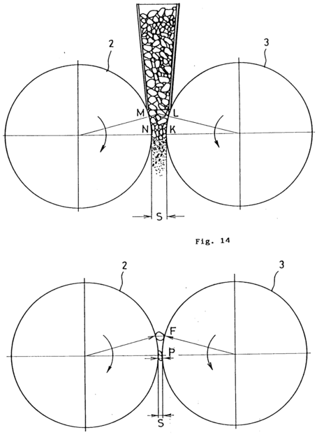
Richards points out that ore may be crushed by rolls in two ways, according to the rate of feed, speed of rolls, &c. If the speed is high and the feed light, each particle of ore is crushed separately between the rolls. In this case, which he calls “free” crushing, there will be a maximum of coarse and a minimum of fine material produced. In “choke” crushing, the ore is fed in a thick stream between the rolls, so that the particles crush each other and a maximum of fine material is produced. Part of the power will be used in compressing the loosely-packed stream. According to Richards, free crushing is the more advantageous course, provided that a very fine product is not required.
The prevailing opinion seems to be that rolls are not economical fine crushers. A certain percentage of the material passing through rolls is crushed very fine, and if the whole product is to be fine, the remainder is sieved out and returned to the rolls. A further quantity, smaller than before, will be sufficiently reduced by the second passage through the rolls. According to Fischer Wilkinson, if fresh coarse ore, equal in quantity to the separated fines, is added to the intermediate product, it is probable that the output will remain constant, and that the power required will be less than in the stamp battery.
Rolls are not generally used to crush finer than about 20 mesh, but Edison proposes to crush to 200 mesh, using choke crushing and corrugated rolls. Corrugated rolls were formerly tried at Mount Morgan and elsewhere, but were abandoned as being of little value, wearing unevenly, and soon getting out of order. Edison’s process appears to necessitate a reduction of comparatively coarse material to excessively fine particles in a single pair of rolls. In general, however, it is considered that gradual reduction in successive pairs of rolls is more economical, the product of one pair of rolls passing to another set slightly closer together. An application of this principle is given in the following description of the Mount Morgan plant, Queensland, formerly in use:
At Mount Morgan the ore was soft and friable (the “Gossan Cap ”), with about 10 per cent, of hard boulders of quartz. It was broken in Krom jaw-breakers (hinge at bottom) to ¾-inch gauge, dried, and then passed successively through four pairs of belted rolls, all running at 112 revolutions per minute. The distances between the faces were 3/8 inch, 3/16 inch, 1/16 inch, and 0 respectively, the first two rolls being 26 inches in diameter and 15 inches wide, and the last two 36 inches in diameter and 16 inches wide. Revolving hexagonal screens or trommels were used after each pair of rolls, the brass screens having 20 holes to the linear inch. The first trommel was protected inside by a steel screen with 16 holes to the square inch. The coarse product was in each case sent to the next pair of rolls. The roll tires were of cast steel, 3 inches thick, and required turning up again in from one to three months. They lasted twelve months, and were discarded when worn down to ½ to 1 inch thick. The wear was 0.108 lb. of steel per ton of ore crushed. The power required was 0.8 I.H.P. per ton crushed in 24 hours. The capacity was 62½ tons per day for each set of 8 rolls, and the total cost, exclusive of lighting, breaking, and drying, was 3s. 10d. per ton. The crushed ore was roasted and chlorinated. The rolls have now been superseded by Krupp ball mills.
A Roll Crusher is massively built; without gears, countershafts, or oil pumps, and with only one moving part. A heavy, annealed, cast steel frame supports the unusually large, accurately finished and polished eccentric shaft, which rotates on heavy duty bearings. The manganese crusher plates are stoutly attached to the front and rear of this frame and are quickly and positively adjustable, while safety plates and absence of any flywheel effect obviate breakage from tramp iron.
Laboratory Roll Crushers usually follow a primary crusher in the crushing section of an ore concentrating mill, and the primary crusher should be operated in closed circuit with a vibrating screen or other sizing mechanism to supply a correctly sized feed for the crushing rolls. The action of the rolls in crushing is continuous and the rate at which they will crush depends upon the reduction ratio, speed of rolls and uniformity and type of feed. The crushing roll is ideally suitable for crushing brittle or friable material and produces a minimum of fines on any type ore.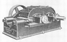
Laboratory Crushing Rolls embody the latest improvements on the ideas of experienced mill men, and at the same time retain simplicity and rugged durability. The main frame and stationary roll journals are cast in one piece, the movable roll is mounted on a heavy sliding saddle and fitted with heavy coil compression springs to provide adjustable crushing pressure between the roll shells.
The roll spacing mechanism may be easily and quickly changed while rolls are in operation, the size of the product changing correspondingly, to permit positive control of product size at all times.
The roll cores are so designed as to provide a continuous bearing surface, accurately tapered on the outside for mounting roll shells, assuring a positive grip that will not slip when shells are worn thin.
Roll shells are made of manganese or chrome alloy steel, depending upon the type of material to be crushed. The outside faces are ground or machined true and smooth for fine grinding and rough ground for coarse grinding. The inside surfaces are accurately tapered to fit the draw-type cores.
Proper lubrication facilities are provided and rolls are furnished with heavy steel plate housing with hopper plates attached, and doors are provided for inspection. The housing can be readily removed.
All types of drives are available: flat belt, “V to V”, or others, depending upon the crushing plant requirements.
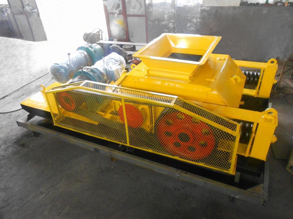
(Spaced Type) are small roll crushers that have been tried and proven over a long period of years by extensive use in the mining industry. Their advantages as a secondary crushing unit are definitely known.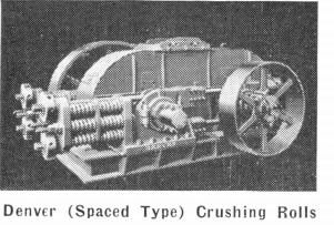
The main frame is constructed of structural steel H beams welded together. Large diameter shafts of heat treated alloy steel prevent failure under severe service and the stationary and movable shafts are interchangeable. Bearings of interchangeable sleeve type have certain self-aligning features that assure equal distribution of bearing load and all bearings are sealed to exclude dust and to retain lubricant.
Cores and shells are positively gripped together and the shells will not slip or break when worn through. tension provides an adjustable crushing pressure from 4,000 to 10,000 pounds per inch of shell face, and the spring pressure is so applied that none is transmitted to the bearings. Tension rods keep the rolls properly spaced for the setting required and the strain on the rods is all tension.
The spacing of the roll shells is accomplished simply by means of a special sleeve nut and spacing may be changed quickly and easily while rolls are in operation. The size of product changes accordingly with change of roll spacing. Absolute control of product size at all times is permitted and this is essential for producing specification material.
Where installations permit, the rolls are furnished with heavy steel plate housings with hopper plates attached, and doors are provided for inspection. The housing can be readily removed when necessary. All types of drives are available; flat belt, V-to-V, or others, depending upon plant requirements.
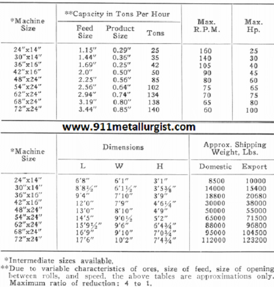
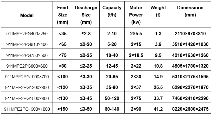
Our production size industrial roll crushers will crush up to 140 TPH depending on the model you select. 
Irrespective of the part which rolls may play in the future in their relation to the two extreme limits of size-reduction, there is no doubt that they have achieved for themselves a secure position in crushing products of intermediate sizes. This is partly due to their large capacity and low cost of operation. It is also due to the fact of their mechanical simplicity, which involves the principle of the toggle-lever in overcoming crushing-strains exerted by particles brought within the angle of nip of their surfaces. Since their revolving masses also serve to absorb their own “ peak-loads ” when properly fed, a moderate and fairly uniform application of driving-power is able to accomplish a considerable amount of effective work in splitting and shattering rock-fragments.
The art of crushing ores and other materials by means of rolls is a comparatively recent one. While the first record of rolls using iron crushing-surfaces dates back to the year 1806, when they were employed in Cornwall, their principal development has taken place during the past 30 years.
To Stephen R. Krom belongs the credit of the pioneer in introducing the belted high-speed roll, which has had its origin and a marked development in this country. His notable contribution to the art was in the use of a single bed-plate or frame supporting the roll-shafts, and to which levers holding the movable roll-bearings were pivoted. He also made use of steel tension-rods to support the crushing-strains, and of hammered- steel tires for the crushing-surfaces. These changes brought the design of crushing-rolls to a high level.
Following closely thereon, about 1885, W. R, Eckart conceived the idea of the swivel or ball-and-socket support for the roll-shaft bearings. This is an excellent mechanical conception, especially for bearings held against a spring pressure, and while it may not be necessary for all types of rolls, yet it has been quite generally adopted by other roll-designers, and illustrates the refinement which roll-construction has now reached.
Other engineers, as, for example, Argali, Vezin, Roger, and Sturtevant, to mention only a few among many, have also given the closest attention to the various details of rolls, such as the frame, springs, bearings, and shafts, and have developed many novel and original designs. It has remained, however, for the boldness and originality of Mr. Edison to extend the field of crushing-rolls in two new directions, and to cause them to exercise new functions. In developing crushing-machinery for his Portland cement works, Mr. Edison constructed “giant” rolls, having a diameter of 6 ft. and a length of face of 7 ft. With these he was not only able to challenge the long-established position of the jaw and the gyratory crushers as primary crushers, but even to leave them well in the rear. By means of projecting knobs on the roll-surfaces he utilized the stored energy of the revolving rolls, and was able to shatter masses of rock of so huge a size that they could not otherwise be made to enter the rolls, thus saving the expense of block-holing and sledging, which is usually charged to quarrying. This work has had successful applications in crushing limestone rock, and there remain also possibilities of the extension of this new use of rolls to rocks of a still harder nature.
In going to the other extreme of size-reduction, Mr. Edison has also utilized rolls in pulverizing cement-rock in his work. For this purpose, rolls with sectional, corrugated, chilled-iron shells 30 in. in diameter and 8-in. face, are provided with shafts 18 in. in diameter, and are forced together with a spring pressure of 100 tons. The feed-material, which has passed a 0.75″ screen-opening, is thus reduced in a single operation to a size at which 94 per cent, passes 100-mesh screen, at the rate of 60 tons per hour. This use of rolls carries the principle of choke-crushing to so extreme a limit as to involve practically a new function. It would appear at first sight, however, that there is less profit-margin for rolls in pulverizing than in mass- reduction, and only a close comparison of the final products obtained and the respective costs per ton can determine the relative economy of rolls for pulverizing when compared with the tube-mill and other types of grinding-apparatus.
Rolls for Coarse Crushing:
Perhaps the most distinctive advantage of rolls is that their construction permits them to apply the principle of “arrested crushing” to a greater range of sizes than is possible with any other type of crushing-apparatus. The crushing-pressure exerted by the opposing roll-surfaces during the angle of nip is instantly released and ceases when the rock-fragments reach the horizontal diameter of the rolls, where the open space between them permits the material to be discharged. Roll- crushing thus permits most careful and accurate stage-reduction within a wide range of sizes, and avoids pulverizing and sliming an undue amount of the softer minerals of an ore, in crushing it to the size at which they will unlock sufficiently from the surrounding gangue to permit their concentration to take place. For those ores, therefore, which require concentration, the use of rolls in preparing them for jigs, shaking-tables, or magnetic separators has become almost the universal practice. This applies to many iron-, copper-, lead-, and zinc-ores. Gold- and certain silver-ores, both those which require concentration and those which do not, are in a class by themselves, since usually their values can be extracted without essential relation to the granular condition of the crushed product.
The modern tendency to reduce milling-costs by increasing the mill-capacity has demanded a greater duty from rolls than ever before, and in the larger mills rolls are now employed from 36 up to 54 in. in diameter, and from 15 to 28 in. width of face. Such rolls are used mainly for coarse crushing ; that is, they take the product from the jaw or the gyratory crusher, from 1.5 to 2.5 in. in size, and reduce it to about 0.5 in. These coarse or No. 1 rolls are then followed by other rolls set closer together for finer crushing, and possibly by others which re-crush certain middlings products obtained in the process of ore-treatment, or even tailings, dependent upon the nature of the ore and its association. Rolls of this general character require massive construction and excellent workmanship. Rolled-steel tires can now be obtained up to 54 in. in diameter. Special hard steels, such as chrome- and manganese-steels, are also used for certain ores, either in the form of tires or of plates bolted to a central mandrel. In this way the life of the crushing-surfaces has been much prolonged.
Marked progress has thus been made within recent years in the field of coarse crushing by means of rolls, in response to the greater demands of modern mill-practice, and this progress has been largely brought about by increasing the dimensions of the rolls and adopting a more massive construction, as well as a better design, combined with a wider choice of steel adapted to different ore-requirements than has heretofore been available.
Rolls for Fine Granulation:
On the other hand, it must be admitted that up to the present time rolls designed for fine crushing, where the ore- requirements demand a maximum granulating effect and a minimum pulverizing or sliming effect upon the crushed product, have made little progress compared with rolls designed for coarse crushing. In fact, rolls, as heretofore designed, can hardly be said to have held their own; and since little assurance of their satisfactory operation can be had in connection with an ore which must be reduced to pass a 20- or 30-mesh screen while retaining the crushed material in a granular condition, rolls have been assailed on all sides by various types of ball-mills and other pulverizing-apparatus which claim to accomplish the function of granulating an ore successfully, but usually by means of some reduction in the time during which the pulverizing effect takes place. While there may be an overlapping territory at the limit of fine granulation where pulverizing-apparatus may be so adjusted as to perform the function of approximate granulation with sufficient success to make their use advisable, yet it is clear that a crushing-force exerted upon material placed between walls which do not touch when at their minimum distance apart, must produce a distinctly better granulated product than when it is crushed between walls which are brought into physical contact with a grinding-pressure.
With the presumption of advantage thus on the side of rolls, even down to the finest sizes, the fact remains that heretofore rolls have proved unsatisfactory and inefficient, from lack of control over the granulating action as the roll-faces wear, and also from their small capacity.
In looking more closely into the cause of this inefficiency, it is evident that the effect of the irregular wear of the roll-faces becomes a more serious matter in fine crushing than in coarse crushing, for the reason that in the former, since the faces must be brought quite close together, the ratio of the sectional area due to irregular wear to the total areal opening between the rolls is greater than in the latter case. Hence any ridging, grooving, or corrugating of the roll-faces permits a considerable proportion of the particles in the feed-stream which enter the depressions to pass between the rolls without being crushed. This reduces the capacity of the rolls, measured by the amount of “ under-size ” or finished product obtained. Another difficulty arising from irregular wear of the roll-faces is due to the fact that when out of parallelism rolls tend to exert a certain component of the crushing-pressure at right angles to the diameter of the rolls, or in the direction of the axes of their shafts. This produces an end-thrust upon the roll-shafts, which, transmitted by means of collars to their bearings, causes them to heat and the shafts to cut, thus absorbing power wastefully, and still further reducing the crushing-efficiency as measured by the power consumed to operate the rolls in relation to the amount of finished product obtained.
Rolls used for fine crushing thus show a decreasing efficiency in proportion to the wear of their roll-faces until a point is reached where it becomes necessary to stop the crushing- operation, and to restore the faces by chipping, grinding, or machining them until their surfaces are parallel. This involves loss of time and of mill-capacity, besides expense and a wasteful use of the roll-shells.
While a certain amount of choke-crushing is usually advisable in fine crushing, in order to offset some loss of capacity, the best results can only be obtained, where the prime object is to granulate an ore, when the roll-faces are maintained parallel, and when the feed consists of sized material in order to avoid packing and pulverizing it in passing it between the rolls. It seems clear from the above considerations that further advance in the art of fine granulation by means of rolls can only be expected by means of certain refinements of function whereby the roll-faces can be maintained parallel while they undergo wear.
Frazee Rolls:
Having had the problem of fine granulation in mind for some time past in its relation to the treatment of certain classes of ores, I have been gratified to find in a recent design of rolls by J. S. Frazee, of Brooklyn, N.Y., that he has completely overcome the obstacles which have heretofore prevented the satisfactory operation of rolls when used for fine crushing, and when a granulated product is required.
Mr. Frazee has given me the privilege of presenting a brief account of his rolls to the Institute; and as I believe they are not generally known, I take pleasure in doing this, in the confident belief that they mark an important step in the advance of the art of roll-crushing.
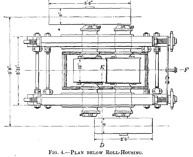
Figs. 1 and 2 show a side and an end view of a pair of 18- by 12-in. rolls. It will be seen from Figs. 3 and 4, which show the same rolls in part sectional elevation and plan, that the bearings of the roll shafts are supported in side-frames. These are of castiron, without tension-rods, and are held together by stay-bolts and lock-nuts to permit the width between the frames to be slightly adjusted, if necessary, when the rolls are in place. This construction has certain advantages for fine crushing over the single bed-plate or frame. It is lighter, less expensive, and permits the rolls to be completely boxed in by means of a wooden housing. This is hoppered at the bottom, and is connected with an exhaust air-pipe, through which the fine dust is drawn by means of a fan, thus keeping the mill-space free from dust. The bearings are of the solid type, lined with babbitt, and each provided with dust-caps at each end. All four are movable in the guides provided for them in the frames. Two of the bearings are held against a spring pressure, and the other two against screw adjusting-bolts, for the purpose of regulating and controlling the space between the roll-faces. These adjusting-bolts are provided with sprocket-wheels and an endless link chain, which is kept taut by means of-a small idler between them. By inserting a long-handled spanner in openings in either of the sprocket-wheels, the adjusting-screws can be moved in exact unison in varying the position of the roll-space.
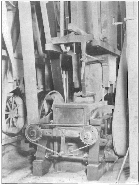
Fig. 2. —End-View of 18- by 12-IN. Frazee Rolls.
This feature has been found a very convenient one, as it permits close and accurate adjustments of the gap between the roll-faces to be made while the rolls are running.
One of the essential features of Mr. Frazee’s design consists, as shown in the illustrations, in making one roll-shell longer
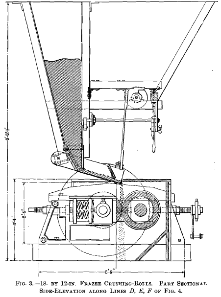
than the other, so as to permit flanges to form on it, between which the shorter roll revolves, with a slight clearance. The rolls are fed from a hopper, which is supported independently of the roll-frame, and in such a position as not to interfere with the removal of the rolls. The lower end of the hopper is made of cast-iron, and is provided with a gate, which is operated by means of a shaft and levers, so that it can be controlled from the forward end of the roll-frame. A feed-tray is placed below the hopper so as to convey the material to be crushed from the hopper-gate to the space between the rolls. This feed-tray is supported at the back of the hopper by a pivot-bolt, which allows it to rotate slightly, and at the front end by means of a wooden connecting-rod to a horizontal arm flexibly connected to a support at the front of the hopper. When the front end of the arm is raised by the teeth of the revolving cam below it,the discharge end of the feed-tray is caused to rise and fall with a jarring or bumping motion.
This causes the material in the feed-tray to be carried forward and to he discharged in a steady stream over the angle-iron which forms a lip or dam at the extreme edge of the tray. The bottom of the feed-tray is made of sheet-steel to permit the material to slide freely. The amount of motion imparted to the end of the feed-tray can he varied by means of an adjusting screw-bolt, which regulates the height of the drop of the horizontal arm, and thereby also the effect of the bumping action upon the feed. A small lever at one side of the adjusting-bolt permits the horizontal arm to be raised above the level of the cam, and in this way the feed can be instantly stopped and started.
It has been a common experience that as rolls are usually fed, even when great care is taken to secure a feed-sheet of uniform thickness, the roll-shells will groove and wear more rapidly at their centers than at their ends. This is frequently caused by a difference in the rate of flow of the feed-stream, owing to friction of the sides of the chute or spout leading from the hopper to the rolls. Another cause of greater wear of the central portion of the roll-shells is the greater mobility of the feed-stream in certain directions than in others, when subjected to a crushing pressure. This difference in mobility causes a difference in the amount of abrasion, and it shows itself by the cupping, grooving, or corrugating of the roll-faces along the center, and by ridging at the edges of the roll-shell. Mr. Frazee has found that the difficulty of irregular wear of the roll-shells can be entirely overcome by a close control over the sectional shape and area of the feed-stream, and by feeding a greater amount of material along the sides of the roll-faces than at their centers.
As shown more clearly on a larger scale in Figs. 5 and 6, the projecting side of the angle-iron which forms the lip of the feed-tray is cut down at its two ends, so as to slope gradually towards the ends, leaving its full height only at the center. In this way the feed-stream passing over the lip or dam is made thicker at the ends than at its center. Furthermore, to regulate the flow and upper contour of the feed-stream, as well as the lower, a guide-plate, which is usually hinged to the sides of the feed-tray, is allowed to rest upon the surface of the feed- stream. This is provided with a wearing-plate at its lower edge, and is so beveled at its two ends as to permit a somewhat greater freedom of flow of the feed-stream at its edges than at its center. The shaded area in Fig. 6 shows the approximate cross-section of the feed-stream, which is adjusted to secure an equal abrading effect across the entire width of the roll-faces, and thus to maintain them in perfect parallelism while they undergo wear. The exact cross-section of the feed- stream will vary somewhat with the hardness of the different materials to be crushed. This can be easily adjusted by varying the amount of bevel given to the edges of the angle-iron and of the guide-plate in the feed-tray until the feed-stream exerts the desired uniform abrading action.
The flanges upon the longer roll-shell perform two functions. They not only confine the feed-stream at its ends, and prevent ridges from forming at the ends of the unflanged roll-shell, but by carrying the feed-stream a slight distance beyond the end of the shorter roll-shell, a small amount of crushing is performed between the sides of the flanges and the ends of the roll-shell. This flange-crushing, being in opposite directions, balances, and all tendency to exert end-thrust of the shafts against their bearings is thus neutralized and overcome. By the simple means thus provided it becomes possible for the roll-tender to maintain the roll-faces parallel while crushing even the hardest material, and to keep the rolls in continuous operation until the roll-shells are completely worn out. The only assistance required of a machinist is occasionally to turn off the edges of the flanges when they become so long that they strike the bolts of the opposite roll which hold its roll- core in place.
Figs. 7 and 8 illustrate the effect of Mr. Frazee’s invention in connection with 12-in. and 24-in. roll-shells, in keeping their surfaces cylindrical until the shells are completely worn out. The 12-in. roll-shell shown in Fig. 7 has been reduced to 6.75 in. in diameter.
The 24-in. roll-shells shown in Fig. 8 have been reduced to 19.25 in. in diameter, leaving a thickness of only 5/8 in. of metal at their edges. At their centers they are somewhat thicker, owing to their beveled inner surfaces, which are required in order to mount them upon their coned centers. A pair of the 24-in. crucible-steel roll-shells, 14.5-in. face, when machined and ready for use, weigh approximately 1,776 lb. When worn down to the size shown in Fig. 8, their weight is 438 lb. The difference—viz., 1,338 lb., or 75.3 per cent, of the original weight—has been entirely expended in useful and effective work. Such a novel and valuable result, whereby the efficiency of the crushing-rolls is maintained uniform while the roll-surfaces undergo wear, clearly marks a step in advance in the art of roll-crushing. The only machine-work required, as already explained, consists in a partial removal of the flanges on the longer roll-shell as the wear of the shells per-
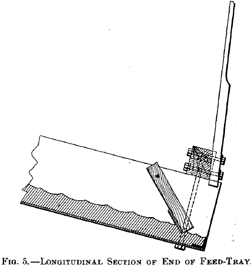
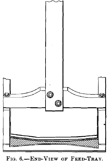
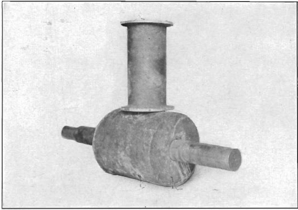
Fig.7- A 12 by 14-in. Roll-Shell, Mounted Upon its Shaft, and a Flanged Roll-Shell of the Same Original Size Worn Down to 6.75 in. in Diameter, its Surface being Maintained Cylindrical without any Machine-Work having been expended upon it.
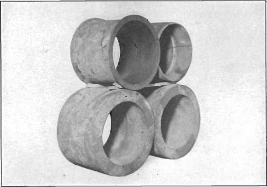
Fig.8- A pair of Worn-Out Roll-Shells Originally 24 in. in Diameter and Reduced to 19.25 in. in Diameter by Wear alone Placed above a pair of 24-in. Steel Roll-Shell Castings.
While the method of feeding the rolls which Mr. Frazee has adopted accomplishes admirably the purpose for which it was designed, and secures a close control over the feed-stream at its point of discharge, it is evident that the same principle might also be adapted to other types of feeders, such as the roller- feeder, the shaking-feeder, the plunger-feeder, the scraping- feeder, etc.
This new roll-design and manner of operating rolls has been developed by Mr. Frazee in connection with the dry crushing of very hard materials used for abrasives, such as quartz, garnet, etc. It is equally applicable to ores, and by the settling and removal of water from the mill-feed, it is possible to apply it to wet crushing as well as dry. The field which is thus opened up in connection with ores which require careful granulation, in order to prepare them for concentration, is a very large one.
Perhaps the most interesting and obvious application of Mr. Frazee’s new roll-design is in connection with the treatment of complex ores. Innumerable processes have been proposed for the recovery of the values contained in these perplexing ore- mixtures, but they may be divided broadly into two classes, viz., that which includes mechanical methods, and that which includes all the others, such as chemical processes, leaching, smelting, etc. While the former are the least expensive, the results heretofore obtained have been proximate only, and the recoveries have shown a low efficiency. All of these mechanical processes, whether they employ gravity, magnetic, electrostatic, or flotation methods (with the single exception of the flotation process adopted by the Minerals Separation Co., Ltd.), require an ore to be crushed to a point where the separate minerals it contains are sufficiently unlocked to permit them to be mechanically separated from each other, so that they may be collected in different groups. The point does not seem to have received sufficient attention, that any one of the above mechanical processes of treating complex ores can be seriously interfered with, if not completely upset, by the means employed to crush such ores in preparing them for treatment.
The mineral association of these mixed sulphide ores is usually a very intimate one, so much so that in many cases it involves crushing them to pass a 30- to 40-mesh screen, or even finer, in order to sufficiently unlock the associated minerals.
By the ordinary methods of crushing there is great danger of producing a large amount of fine powder, or slime, in crushing to such sizes. Particles of a very minute size, usually placed at about 200-mesh, then become, in a measure, a law unto themselves, and the losses in treating such material are very great. The obvious way to solve the dust, or slime, problem is not to make any dust, or slime, or as little as possible, in crushing these ores for mechanical separation.
The future of the mechanical processes of ore-treatment, in competition with others which promise larger returns, will thus depend, in many cases, upon successful granulation. In this direction I believe that Mr. Frazee’s invention, as outlined above, has accomplished a great step in advance in the art of roll-crushing, and it holds out great hopes for the future in the more successful preparation of many ores for mechanical concentration, by reason of the control he has secured over the wear of his roll-shells, whereby a better granulating action can be obtained.
Progress in Roll-Crushing. BY C. Q. Payne, New York, N. Y.
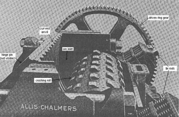
On the right, a Roll Crushers is shown in a sectional elevation of the A-C single-roll crusher while here below is a cutaway view of the machine, with hopper and part of the near side frame removed to show the crushing chamber. The moving elements of the machine consist of the roll, with its supporting shaft and driving gear, and the pinion-shaft on which are mounted the pinion and driving pulley. The fixed member of the roll crushing chamber, known as the anvil, is supported near its upper end by a heavy cross-shaft; the lower end is held in position by a transverse equalizer beam (anvil beam), to each end. of which is attached a pair of heavy tie-rods. These rods, at their upper ends, pass through two nests of strong springs, which serve the double purpose of shock absorption, and equalization of tension on the rods. The anvil is positioned at its lower end by shims, placed between the ends of the anvil beam and the side frames. The entire mechanism is supported by the pair of heavy and rigid side frames, which are tied together by stiff cross-members at each end.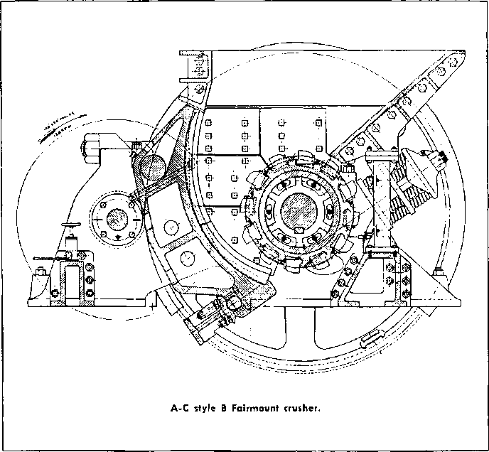
The curved crushing surface of the anvil is lined with chilled-iron or manganese-steel concaves, which are cast with corrugated faces. These corrugations sometimes extend the full length of the surface, but when a fine product is desired the lower concave segments are made with a flat surface at the discharge point. The roll-centre is made of cast steel, and the teeth are of manganese steel inserted in cored pockets in the surface of the roll-centre. These teeth, it will be noted, are of different heights, the higher teeth being known as “slugger teeth,” and the lower ones as “regular teeth.”
 Roll Crushing Action and Working Principle
The tip-velocity of the slugger teeth in the Fairmount-style crusher is from 400 to 450 ft/minute, or in the neighbourhood of 7 ft/second. The working faces of the teeth are radial in profile, which means that the faces are normal to the line of action when a rock is contacted in any part of the crushing chamber.
When a mixed load of quarry-run stone is dumped into the hopper of the single-roll crusher the following stages may be observed: first, there is a pronounced selective segregation; the entire load is subjected to vigorous agitation, causing the smaller pieces of stone to sift down through the mass of material into the crushing chamber, where they are reduced by a succession of sledging impulses from both regular and slugger teeth as the broken and re-broken pieces are worked down the curved face of the anvil to the discharge point. During this stage, if there is any considerable amount of fine material in the load, the large pieces of rock are shoved up and held away from the roll by the mass of smaller pieces. As the crusher clears itself of the small stone the larger blocks come down into the zone of action. Here, too, there is a certain degree of segregation; the crusher seems to have an uncanny faculty of weeding out the small fry, then the middleweights, and finally taking on the heavyweights.
Unless the stone is of a friable nature very little breaking is done on top of the roll, i.e., by pure impact action; therefore these machines are not suited for crushing stone of massive or blocky structure. They are highly effective on stratified rock, where the maximum thickness of ledge is within the dimension which can be nipped between the advancing slugger teeth and the anvil. Working on such stone, the crusher will handle any size piece that will enter the upper part of the crushing chamber. Large slabs which lodge against the anvil at their lower end are fractured by the action of the slugger teeth beneath them, or are up-ended and thrown against the anvil and the back of the hopper, where they are held while the slugger teeth work on them from the bottom.
Naturally, during the action we have described, the agitation in and above the crushing zone is quite violent, and therein lies an outstanding feature of this crusher. The continuous heaving of the material minimizes bridging, making the crusher to a large extent self-feeding. Such bridges as do occur can frequently be broken by the simple expedient of throwing in a single piece of stone of sufficient size to raise the bridged material as the stone passes underneath it. Bridges may also be broken by dumping a load of small rock into the crusher; the selective action we have described will generally break the bridge unless the bridged pieces are very firmly wedged. Blockades caused by single pieces of stone too large to enter the crusher are a more serious matter, and are usually more difficult to break than in the gyratory or jaw crusher, due to the fact that the process requires some care to minimize the element of personal danger.
On the soft and medium grades of stone, to which the single-roll crusher is particularly well adapted, the machine will turn out a product carrying less fines than will either the jaw or gyratory types; in fact, the product of the single-roll machine on soft rock will generally compare favourably, on this score, with that of the other two types on hard rock. There is no tendency to build up a packed condition in the lower part of the crushing chamber; rock reaching this lower zone is quickly and forcibly discharged. Moreover, the selective characteristic of the crusher minimizes attritional action by getting the fine material out of the way quickly, and most of the crushing is done by clean, sharp sledging blows against the individual pieces.
The size of product is governed by the distance between the roll and the tip of the concaves at the lower end of the anvil, which corresponds to the open-side discharge setting of the jaw and gyratory types. There will of course be some difference in the size of product, depending upon whether the concaves are smooth or corrugated at the discharge point. With smooth concaves, and operating on soft or medium stone, the product will average from 80 to 85% passing a square opening equivalent to the discharge setting. With corrugated concaves the product will be somewhat coarser. If the rook is hard the lower end of the anvil will be forced away from the roll a little when the crusher is fully loaded, due to compression of the springs, and this may increase the square-opening size of product by as much as 1″.
The single-roll crusher is essentially a primary crusher, and general results will be better if the installation is engineered with that thought in mind. The machine will function more satisfactorily and economically when fitted with corrugated concaves, and set for a medium or coarse product, than when fitted with concaves which are smooth at the discharge point, and set “tip-to-tip.”
 Optimal Roll Crusher Feed Size
Unless the rock is exceptionally friable the maximum thickness of the feed should not exceed that thickness which the crusher can effectively nip between the advancing slugger teeth and upper part of the anvil; the only breaking done on top of the roll should be the beam action breaking of long slabs. For that reason the maximum advisable thickness of ledge is established by the distance between the face of the anvil, and the point of contact on the face of the roll where the teeth can get a full “bite” on the rock. This of course is a function of the roll diameter, which governs the general proportions of the crushing chamber.
The 24″ diameter roll crusher has an effective nip of about 14″ maximum; the 36″ machine will grip stone up to about 24″ maximum; and the 60″ crusher will handle ledges up to about 36″ thickness. These thickness are based on limestone of medium hardness; for harder materials the advisable thickness is somewhat less. So far as width is concerned, the crusher will handle any piece that will enter into the crushing chamber between the side liners. There is no practical limitation to the length of the feed, so far as the crusher itself is concerned. If the piece is not too thick the machine will break any rock that can be manoeuvred end-on into the crushing chamber.
The capacity of the single-roll crusher is influenced by the nature of the feed to a much greater extent than is the case with any of the types discussed heretofore. The two factors which have a very important bearing on capacity are thickness and hardness, or toughness. Blocky material which must be broken on top of the roll will, unless the stone is very friable, require a considerable amount of hammering by the slugger teeth to reduce the blocks to sizes that can be gripped between the teeth and the anvil all of which is a time consuming process. The harder the material is, the more time will be consumed in such impact breaking. Hardness or toughness also has a retarding effect upon the sledging action on the smaller pieces of material; instead of shattering, as soft rock will under these sledging blows, the harder material snaps off in small pieces at the point of impact, which means that more blows are required to reduce each individual block (a time consuming operation).
Because the action of the crusher is of this nature, it is not practicable to give the various crusher sizes a unit capacity rating to correspond to each discharge setting, or product size, as can be done with reasonable accuracy for the gyratory and jaw types. It is necessary to predicate the ratings upon selected values of hardness and maximum thickness of the feed, as well as the discharge setting. It has been done for four sizes of the single roll crusher. The material upon which this table is based is a medium limestone, of 8000 to 10,000 PSI crushing strength. On this basis ratings are given for different thicknesses of feed, and for different product sizes.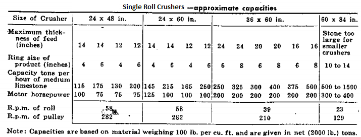
The single-roll crusher, as compared to the gyratory and jaw types, has a rather limited field of application, and being a “specialist” it is only fitting that it should be exceptionally proficient in the field for which it is adapted. It is a highly effective primary breaker for such materials as the soft-to-medium limestones, dolomite, magnesite, phosphate rock, cement rock and shales. It is decidedly not a hard-rock crusher, nor is it suited for rock of massive or blocky structure unless it is, at the same time, of friable texture. Practice is to limit its application to rock having a crushing strength not exceeding 15,000 PSI.
During the crushing process, particularly when material is riding on the roll, there is considerable slip or rubbing action between the material and the tops of the teeth, and this will obviously result in rapid wear if the rock is at all abrasive. For that reason this crusher is not economically suited to the handling of rock containing more than a few percent of free silica unless, again, it is very soft and friable. By virtue of its positive discharge characteristic the single-roll crusher ranks as a top performer in the handling of wet and sticky material, and it will take care of stone containing a substantial admixture of loam or clay. In this respect we would rate the currently leading types of primary breakers in the following order:
Some very soft materials for example, do not handle well in the single-roll crusher, clinging to the anvil and refusing to work down into contact with the teeth. Clay and similar sticky material will of course behave in the same manner, but if there are enough pieces of solid rock in the load, the machine will keep itself clean by using the rock as a scouring agent. Because it is a proficient self-feeder the Fairmount crusher may be fed directly from cars or trucks, discharging into a plate steel super hopper of suitable proportions, this hopper being superimposed on the heavy cast hopper which is a part of the machine. If the loads are not too large with respect to the size of the crusher, the entire load may be dumped at once, without much risk of bridging. For very large cars or trucks controlled dumping is preferable.
